CatchmentSIM is useful for mapping flow paths and subcatchments in the urban environment. The software performs well in urban areas because of 3 algorithms, specifically:
1.Flow Path Mapping: CatchmentSIM's flow path mapping algorithm allows drainage to propagate at any angle rather than the D8 algorithm adopted by most terrain analysis packages which only allow 8 possible flow directions. This can have a significant impact on flow paths in urban environments.
2.The Breaching Algorithm: This algorithm removes flat and pit cells from the DEM by simulating ponding and finding the lowest point for overtopping which gives better results than other flat and pit removal algorithms which simply look at the flow direction of nearby cells.
3.The Pit Algorithm: CatchmentSIM also includes a revised version of the Breaching Algorithm which allows flats and pits to be removed while preserving sag points within the DEM. This represents an advantage over other approaches which will fill or breach sag points resulting in unrealistic overland drainage.
This page describes how CatchmentSIM can be used to model flow in the urban environment to map catchments and flow paths associated with stormwater pits. This page also includes instructions regarding integration with the 12d Civil Design software packages (www.12d.com), however, the same techniques can be used on any urban dataset.
Part 1 outlines how fence lines can be modelled in CatchmentSIM, and how pit catchments, longest flow paths and imperviousness characteristics can be quickly determined for an existing drainage network.
Part 2 outlines how CatchmentSIM can be used to analyse the hydrologic attributes of the terrain to help design a drainage network from scratch including identification of sag points, inter-allotment drainage and automatic pit placement.
Part 1) Modelling fence lines and Development of Catchments for An Existing Network
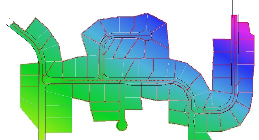
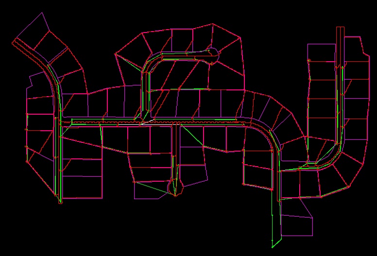
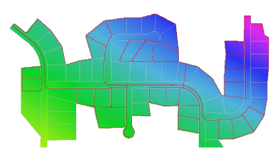
Consider the urban sub-division and drainage network illustrated below in the 12d screenshot. The aim is to automatically determine the pit catchments, longest flow paths and impervious proportions for each of the stormwater pits in the green network based on the underlying design TIN, property boundaries and existing network.
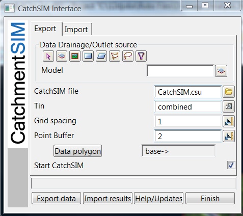
The first step is to export the relevant data to CatchmentSIM using the 12d integration macro (available from our training site). We select the stormwater network (SWNetwork1), the design TIN (combined) and the DEM resolution.

Click to Enlarge Image
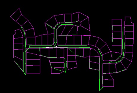
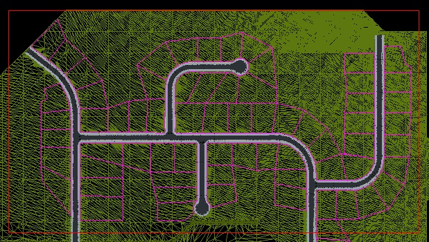
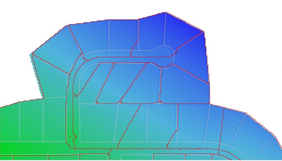
Once the Export Data button is clicked the CatchmentSIM project will be automatically setup and the pits imported as outlets (these look like red "+" signs due to the pixel buffer). The only further steps that were undertaken to produce the image below were the addition of the fence line (property boundary layer minus front lines) and road layers to the display.
| Note: | If you were not using the 12d macro for this, you would need to start a new project (CatchmentSIM Drop Down >> New Project), setup a blank DEM (Create DEM >> Setup Blank DEM), sample the TIN (Create DEM >> TIN) and import the stormwater pits as outlets (Subcatchments >> Import Outlets). |
At this point we wish to 'enforce' the fence lines into the DEM since they are not picked up in the design TIN. To do this, we use the DEM Conditioning >> Vector Dataset Operations command. In this case, we ask the fence lines layer to be reverse burnt into the DEM by 0.25 m with a 1 pixel buffer.

Click to Enlarge Image
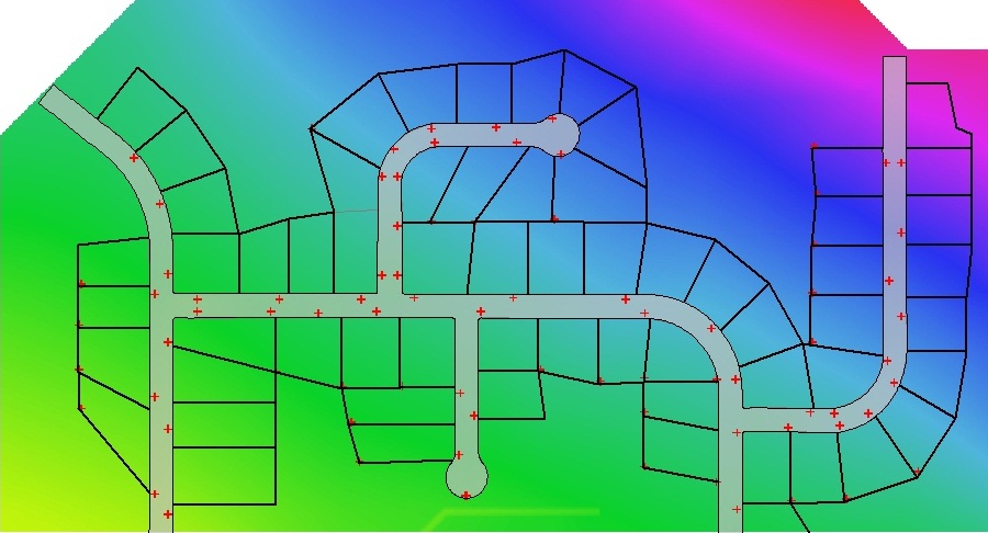
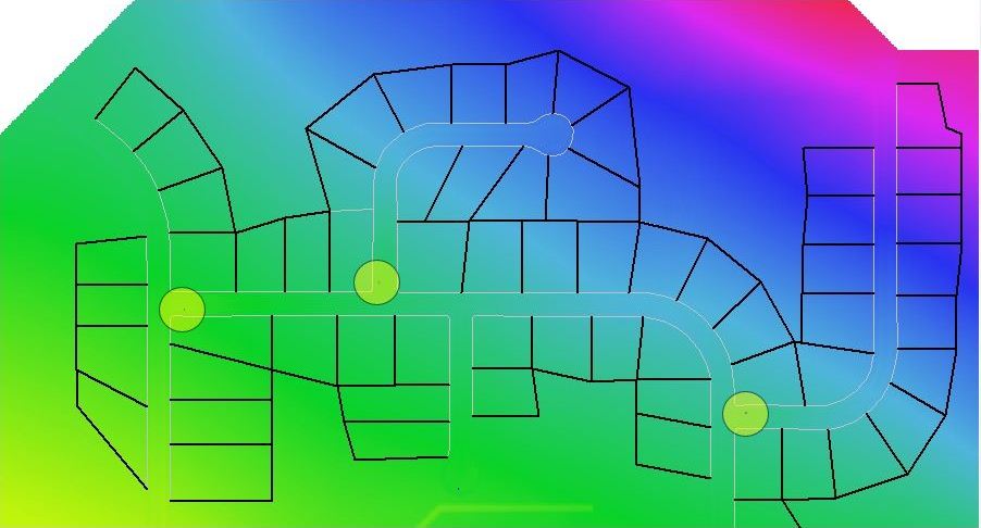
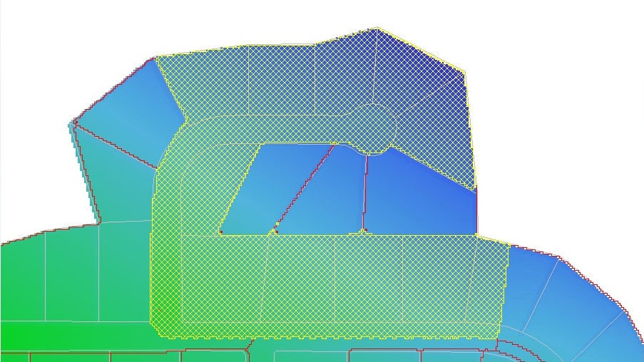
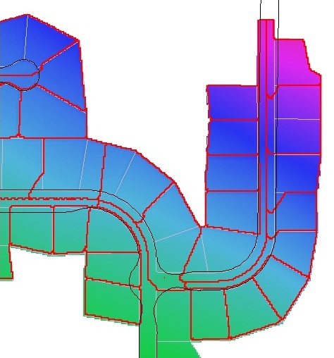
At this point, we decide to remove all the terrain outside the developed area (assuming that alternative drainage will be provided for this area) using DEM Conditioning >> Miscellaneous >> Apply Clip Mask to DEM and use a fence layer created from the roads and property boundary layers. We also remove the flat and pits from the DEM while preserving sag points using the Auto Flat/Pit Removal Algorithm (DEM Conditioning >> Auto Flat / Pit Removal). Next the catchments and longest flow paths can be automatically mapped using the Subcatchments >> Map All command. The result can be seen in the image below.
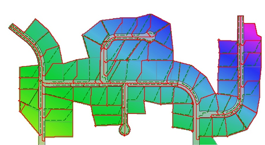
These results can be immediately exported back to 12d using the Export >> 12D >> 12d Catchments command. They can then be immediately linked to the drainage network in the network editor.
However, we may first wish to determine impervious proportions for each catchment before exporting the results. For example, we can import the road polygon and assign it 100% impervious and then import the property boundary polygons and assign them 50% impervious. CatchmentSIM will then automatically calculate the average impervious proportion for each catchment. These functions are provided by the Impervious Areas manager (GIS >> Impervious Area).

Click to Enlarge Image
The impervious proportion values for each catchment can be seen in the Subcatchment Manager (Subcatchments >> Subcatchment Manager) as shown below.

Click to Enlarge Image
This example has aimed to demonstrate how a subcatchment and flow path network can be quickly developed for an existing stormwater network (in 12d or other software) taking account of fence lines and impervious proportions. The next part outlines how CatchmentSIM can be used in the absence of a drainage network to help identify suitable stormwater pit locations.
Part 2) terrain analysis - sag pits and inter-allotment drainage
In this example, let's assume that we have a design TIN, property boundary outline and road polygon in 12d and wish to start building a drainage network.
The first step is to export the relevant data to CatchmentSIM using the 12d integration macro (available from our training site). In this case, we do not select a drainage network, however we do select the design TIN (combined) and adopt a DEM resolution (1m).
Once the Export Data button is clicked the CatchmentSIM project will be automatically setup. The only further steps that were undertaken to produce the image below where the addition of the fence line (property boundary layer minus front lines) and road layers to the display.
| Note: | If you were not using the 12d macro for this, you would need to start a new project (CatchmentSIM Drop Down >> New Project), setup a blank DEM (Create DEM >> Setup Blank DEM) and sample the TIN (Create DEM >> TIN ). |

At this point, we can display the flat (red) and pit (blue) locations as shown below.

However, most of these will be localised depressions of a few millimetres. We want to identify if there are genuine sag points in the terrain that we need to account for. To do this we apply the Breaching Algorithm (DEM Conditioning >> Breaching Algorithm). We need to select the Max Elevation Gain option and enter the maximum amount of ponding we are prepared to tolerate. For example, in this case we have selected 100mm as the threshold. Depressions that will overtop with less that 100mm of ponding will be removed and those with greater ponding will remain.

Click to Enlarge Image
After application of the Breaching Algorithm, it can be seen that only 3 sag points remain (highlighted below). It will be necessary to provide drainage at these locations.
At this point, we may also wish to examine the need for inter-allotment drainage. This can be done in a similar manner, however we must first 'enforce' the fence lines into the DEM so we can visualise the areas where fence lines may create a need for inter-allotment drainage. We can use the Vector Data Set Operations (DEM Conditioning >> Vector Data Set Operations) to raise the elevations of all DEM pixels underlying a fence line by a set increment (0.25m).

Click to Enlarge Image
After applying the Vector Data Set Operations, we can again remove localised depressions by applying the Breaching Algorithm with a Max Elevation Gain threshold.

Click to Enlarge Image
At this point, we can see that there are a number of new sag points created indicating the need for inter-allotment drainage (highlighted below).

We can now add these sag points as outlet locations (ultimately nodes in the drainage network) using the Subcatchments >> Other >> Add Flats and Pits as Outlets command.

Click to Enlarge Image
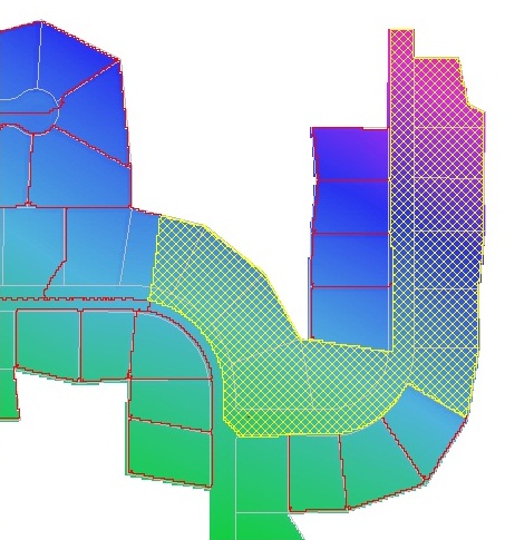
The subcatchment network relating to these points can be mapped using the Subcatchments >> Map All command as shown below.
It can be seen that the original 3 sag points on the road have very large catchments. It will be necessary to further breakup these catchments by placing additional outlets (expanding the drainage network).
This can be done using the Subcatchments >> Breakup Subcatchment command. We can set a target size (eg 0.25 hectares) and CatchmentSIM will try to place additional outlet to create catchments of the selected size.

Click to Enlarge Image
The new subcatchments and outlet (pit) locations can be seen below.
You may also wish to have further control over the automatic placement of outlets by the Catchment Breakup algorithm by providing set-out lines for the outlets. These can be introduced by selecting the Target Zone checkbox in the dialog.
The image below shows the set-out lines and the subcatchments created when the highlighted catchment above was broken up using the Catchment Breakup Algorithm.
Using these approaches, the catchments (and longest flow paths) can be exported back to 12d (or other civil design software) to aid the designer in creating a drainage network.