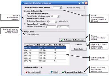
The Breakup Subcatchment form allows discretisation of a previously mapped catchment or subcatchment into a number of smaller subcatchments based on one of three catchment breakup approaches
•Flow Accumulation Analysis;
•Horton Order Analysis; and,
•Subcatchment Target Size.
The catchment or subcatchment to be discretised can be selected by either typing in its integer code (the number in the first row of the Subcatchment Manager form) or clicking From DEM which allows the subcatchment to be manually selected by left mouse click when the subcatchment is highlighted.
The Flow Accumulation Analysis catchment breakup methodology allows the user to select a designated number (odd number) of subcatchments into which to break the identified catchment or subcatchment. CatchmentSIM will process all the pixels within the DEM that have a flow accumulation greater than an internal minimum threshold. These pixels will be analysed to rank the largest jumps in flow accumulation value (number of pixels upstream of the pixel) between a pixel and its next downstream pixel. These flow accumulation jumps identify points of significant lateral inflow indicating the input of a tributary. Once the lateral inflows have been ranked then the x largest flow accumulation jumps will be selected to be mapped to generate the required number of subcatchments (x is typically the target number of subcatchment divided by 2). In order to map both the upstream subcatchment and the tributary catchment, CatchmentSIM will place a single pixel subcatchment outlet at each of the upstream and downstream pixels corresponding to the lateral inflow, hence creating two subcatchments.
| Note: | For this algorithm to work properly, stream burning may be necessary (DEM Conditioning >> Burn Streams). Please note, if stream burning is carried out after flow processing, then flow processing must be re-run (Subcatchments >> Map All) before its effect on the Flow Accumulation Analysis can be seem. |
The Horton Order based catchment breakup algorithm aims to delineate subcatchments of a particular Horton order based on the vector stream network. For more information on generating a vector stream network, see Flow Mapping >> Generate Streams and display of vector streams of different Horton Order refer to the View Attributes form.
You should have already generated an appropriate vector stream network prior to running this algorithm, however, CatchmentSIM will prompt you for the SAT and MSCL parameters required to generate a vector stream network if one does not exist.
The algorithm aims to place a subcatchment outlet pixel above and below the lateral inflow corresponding to a tributary that is greater than the selected threshold Horton order. For example, if a user wishes to delineate all 3rd order subcatchments or higher then a dual outlet will be placed wherever two 3rd order (or higher) vector stream segments intersect such as a 3rd and 4th order intersection but not a 3rd and 2nd order intersection. Using this algorithm does not allow the user to designate the exact number of new subcatchments, however, reducing the order delineation threshold will increase the number of dual outlets in the table and thus the number of subcatchments.
A comparison of the automated catchment breakup algorithms can be seen in the Key Challenges section.
Regardless of which subcatchment breakup algorithm is adopted, after clicking Process Subcatchment the table will be populated with the suggested dual outlets. The lateral inflow column refers to the difference in flow accumulation between the upstream and downstream pixels, that is, the number of pixels in the tributary. If accepted, an outlet will be placed at each of the upstream and downstream pixels as listed. Dual outlets can be removed if you do not wish to delineate them, such as if one is very close to another or the lateral inflow is not significant enough.
Once satisfied with the suggested dual outlets, click Accept New Subcatchment and the new outlets will be introduced. You will be prompted to reprocess flow paths for all pixels within the subcatchment being broken. This is synonymous with the Subcatchments >> Reprocess Subcatchment menu option and is recommended to update the subcatchment mapping and derived parameters.
Subcatchment Target Size
When using the subcatchment target size algorithm (Subcatchments >> Breakup Subcatchment), the user designates a target subcatchment size. The algorithm will automatically breakup the catchment into the number of subcatchments necessary to meet the target subcatchment size.
The target subcatchment size is specified as a number of pixels or an area (e.g., hectares).
The subcatchment target size algorithm may be useful in the design of drainage infrastructure. For example, if a contributing catchment area can be correlated with the capacity of a standard stormwater inlet pit, the target size algorithm could automatically subdivide the catchment to meet the contributing catchment area threshold. The subcatchment outlet points determined by the algorithm would correspond to the optimal location for the standard stormwater inlet pits.
