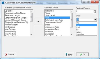
ID Number
|
Integer ID of the subcatchment, used instead of subcatchment name when the subcatchment network is discontinuous (ie., more than one catchment outlet).
|
Name
|
Subcatchment name assigned in nodal network arrangement (refer to Project Options | Subcatchment Labelling for labelling parameters).
|
User Label
|
A user label imported or assigned to a subcatchment
|
Area
|
The subcatchment area
|
Total Upstream Area
|
The total upstream area for the subcatchment
|
Up Subs
|
The names of immediately upstream subcatchments
|
Downstream Sub Name
|
The name of the immediately downstream subcatchment
|
Downstream Sub ID
|
The ID of the immediately downstream subcatchment
|
Slope
|
Subcatchment slope as calculated by weighted average (by flowpath length) of a set sample size (refer Project Options form) of average vectored slope calculations for pixels on the perimeter of subcatchment.
|
Hill Slope
|
Hill slope as calculated by weighted average (by flowpath length) of a set sample size (refer Project Options form) of average vectored slope calculations for pixels on the perimeter of subcatchment for that portion of their flowpaths until a pixel with a contributing catchment greater than the current Stream Area Threshold (SAT) is reached.
|
Impervious Area
|
Impervious area within subcatchment as calculated by rasterisation of impervious polygons, and consideration of background impervious parameter.
|
Impervious Prop
|
Impervious proportion of subcatchment as calculated by impervious area (above) divided by total area expressed as a percentage.
|
Perimeter Length
|
Length of the subcatchment perimeter formed by combination of outer edge lengths of all subcatchment perimeter pixels.
|
Horton DD
|
Horton drainage density as calculated from the vector stream network length within the subcatchment divided by subcatchment area.
|
Bifurcation
|
Bifurcation ratio calculated for subcatchment based on vector stream network.
|
Main Stream Length
|
For self-contained subcatchments (ie., no upstream input) the main stream length is defined as the longest flow path in the subcatchment. For subcatchments with one or more upstream input subcatchments, the main stream length is defined as the longest stream segment within the subcatchment which is from an upstream subcatchment.
|
Main Stream Slope
|
The average vectored slope of the main stream defined above, expressed as a percentage.
|
Longest Flowpath Length
|
The length of the longest flow path within the subcatchment
|
Longest Flowpath Slope
|
The average vectored slope of the longest flow path
|
Shape (Area/Perimeter^2)
|
The shape parameter is defined as the subcatchment area divided by the perimeter length squared and is dimensionless.
|
Lake Area
|
The area of defined lakes within the catchment.
|
Lake Prop
|
The proportion of subcatchment area covered by defined lakes.
|
Network Depth
|
Maximum number of subcatchments a flow path may traverse to reach outlet of this subcatchment.
|
Min Easting
|
The minimum easting of the subcatchment
|
Max Easting
|
The maximum easting of the subcatchment
|
Min Northing
|
The minimum northing of the subcatchment
|
Max Northing
|
The maximum northing of the subcatchment
|
Centre Easting
|
The centroid easting of the subcatchment
|
Centre Northing
|
The centroid northing of the subcatchment
|
Outlet Easting
|
The outlet centroid easting
|
Outlet Northing
|
The outlet centroid northing
|
Max Elev
|
The maximum elevation of the subcatchment
|
Min Elev
|
The minimum elevation of the subcatchment
|
Vert Range
|
The vertical range of the subcatchment
|
Mean Elev
|
The average elevation of the subcatchment
|
Median Elev
|
The median elevation of the subctachment
|
Elev Std Dev
|
The standard deviation of the subcatchment
|
Overflow Pixel
|
The overflow pixel of the subcatchment (if a subcatchment has no downstream connectivity and the lowest point on the perimeter borders another subcatchment then it is deemed to have an overflow)
|
Ponding Depth
|
The depth of ponding prior to subcatchment boundary overflow
|
Overflow Sub ID
|
The subcatchment ID of the downstream overflow subcatchment
|
Overflow Elevation
|
The elevation of the overflow pixel
|
Processing Order
|
The order in which a subcatchment should be processed to ensure no subcatchment is processed before while an upstream subcatchment is not yet processed.
|
Avg Flow Length
|
The average of the flow path lengths to the subcatchment outlet for all pixels in the subcatchment. Please note, this value does not take Smoothing into account.
|
Flow Length Std Dev
|
Standard deviation of the flow path lengths to the subcatchment outlet for all pixels in the subcatchment. Please note, this value does not take Smoothing into account.
|
Channel Skew
|
Calculated as:
Sk = (A2 - A1) / A
Where:
Sk = channel skew factor
A1 = subcatchment area to one side of the channel
A2 = subcatchment area to other side of the channel
A = total subcatchment area
|
Subcatchment Width
|
Calculated as:
W = (2 - Sk) * L
Where:
W = subcatchment width
Sk = channel skew factor (refer above)
L = length of main drainage channel
|
Main Stream S1085%
|
The main stream slope estimated by measuring the distance and change in elevation between two points located 10% and 85% of the distance along the channel from the subcatchment outlet. It can be used to estimate the average main stream slope, however, the Main Stream Slope variable will provide a more reliable estimate.
|
