Download Tutorial 4 Data and Solution File
Tutorial 4 shows the user how to use CatchmentSIM to map catchment for stormwater pits, particularly in association with the 12d Model. The tutorial shows how to setup a CatchmentSIM project using 12d TIN data, condition the DEM and export the delineated subcatchments and associated subcatchment parameters back into 12d for further detailed drainage analysis.
12d Integration
Refer to the 12d tab on the CatchmentSIM page for the most up to date information regarding the 12d integration script.
The 12d integration script will produce a CatchmentSIM Setup File (*.csu) which can be opened in CatchmentSIM by selecting CatchmentSIM Drop Down >> Open Project. Ensure that 'CatchmentSIM Setup File (*.csu)' is selected in the 'File of type' drop down box. Alternatively, you can open the 'Tutorial 3.csu' file if you do not have access to the 12d software.
As shown below, the CSU file will automatically setup a blank DEM, assign elevations to the DEM by sampling the 12d TIN and incorporate the location of stormwater pits as subcatchment outlets.

Click to Enlarge Image
incorporate 12d data into catchmentsim
Once you have the project setup as shown below, you can begin to process the pit catchments.
hydrologic treatment of dem
Although a DEM has been developed based on the 12d TIN, it may not yet be ready for use to delineate the subcatchments draining to each stormwater pit. The DEM will probably contain some flat or pit pixels, that is, pixels that are either equal or lower in elevation than the lowest of their neighbouring pixels.
A Pit Algorithm is incorporated into CatchmentSIM to resolve flat and pit pixels in the DEM while preserving localised depressions that may serve as subcatchment outlets in an urban stormwater setting (e.g., stormwater sag pits, detention basins etc).
Select DEM Conditioning >> Pit Algorithm to run the Pit Algorithm. After completion of this algorithm you should notice that the flat and pit pixels have been mapped to an optimised downslope outlet pixel and this is indicated on screen by a yellow line. Pixel elevations along this line have been linearly lowered to provide a downslope flow-path for the original flat or pit pixel. If you redraw the screen (F5) and select 'Flats and Pits' from the Layer Controller you should notice that only one 'pit' now exists within the expected catchment boundary. This pit pixel corresponds to a local drainage depression and has been retained in the DEM in order to represent a sag pit at this location.
SUBCATCHMENT MAPPING FOR ROADS
At this stage your DEM should be ready for use in mapping subcatchment boundaries. To test flow routing on the DEM try mapping flow from a selection of pixels within the roadway. Do this by selecting Flow Mapping >> Map Pixel Flow Path and clicking on some points on the screen that you expect to drain to each of the stormwater pits.
As outlined above, the CatchmentSIM Setup File has already incorporated stormwater pits as subcatchment outlets. To map the subcatchment draining to each stormwater pit select Subcatchment >> Map All. The mapped subcatchment boundaries should appear in red as shown below.

Click to Enlarge Image
IMPERVIOUS POLYGONS FOR ROADS
The road network represents a significant impervious area and should be incorporated into the CatchmentSIM project. Select the GIS >> Impervious Areas menu and then select Import Polygon(s). Locate and select the file 'imp areas.mif'. A dialog box will then require you to identify data columns in the GIS data-set that correspond to the polygon description and impervious proportion fields. Select 'none' for both fields. The roads impervious area polygon will now be incorporated into CatchmentSIM project as a translucent grey polygon (refer image below).

Click to Enlarge Image
The impervious proportion assigned to each subcatchment will now be updated to 100% to reflect the new impervious area polygon. The subcatchment properties can be reviewed by selecting Subcatchments >> Subcatchment Manager.
SAMPLING OF ADDITIONAL 12d TIN DEM DATA
The images shown above indicate that subcatchments have only been mapped for the roadways. This is because DEM elevations have not been assigned to areas outside of the roadway. This methodology is suitable if drainage infrastructure is already in place to drain areas external to the roadway. However, what happens if the stormwater drainage system in the roadway needs to be designed to cater for runoff originating from outside of the roadway?
To address this issue it is necessary to incorporate additional topographic information in areas outside of the roadway. In this instance we will sample a 12d TIN DEM to fill all of the 'white space' in the current DEM.
Select Create DEM >> TIN and locate the 'existing survey.12da' TIN and click 'Open'. CatchmentSIM will then assign raster DEM elevations for all 'blank' DEM pixels (i.e., all pixels outside of the roadway). The new DEM should look similar to the image shown below.
REMAPPING of SUBCATCHMENTS WITH ADDITIONAL DEM DATA
Now that the additional DEM data is incorporated in CatchmentSIM, it is necessary to remap the subcatchments draining to each stormwater pit. To remap the subcatchments select Subcatchments >> Map All. The remapped subcatchment boundaries should appear in red as shown below.

Click to Enlarge Image
If you look again in the Subcatchments >> Subcatchment Manager, you should see that the impervious proportions have been updated accordingly.
Restricting flow to roads and lots
You may wish to restrict the drainage mapping to a particular area, for example the lot boundaries. The image below illustrates the project with the lot and road boundaries added as a vector layer.

Click to Enlarge Image
To restrict the drainage catchments to these areas, select DEM Conditioning >> Miscellaneous >> Apply Clip Mask to DEM and select the 'lots and roads' mid/mif file. Following this, reprocess the catchments using Subcatchments >> Map All. You can also turn on the 'Longest Flow Paths' layer in the layer Controller if you wish as show below (dashed blue line). The attributes of these lines are also exported to 12d.

Click to Enlarge Image
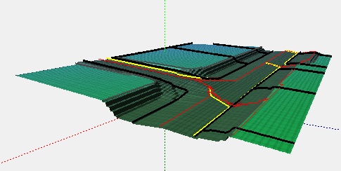
You can also visulalise the road drainage in 3D using the Utilities >> Show 3D Viewer tool.
exporting DATA FROM CATCHMENTSIM to 12d
To export the delineated subcatchment boundaries and associated parameters from CatchmentSIM into 12d select Export >> 12D. You will be prompted to select a file name for the outputs. Please refer to the Training Site for the most up to date information regarding importing the data back into 12d.
auto Placement of Pit Outlets
We can see that on of the catchments is very large and more pits will be needed in this area. CatchmentSIM can help with this by automatically placing outlets to create subcatchments of similar user designated sizes. For example, go to the Subcatchment Breakup form (Subcatchments >> Breakup Subcatchment). Ensure the correct subcatchment is selected, click on Select From Display and click on the largest subcatchment. Select the Subcatchment Target Size option and enter 3000 pixels (in this example = 3000 m2). Select 'Process Subcatchment'. Next select 'Accept New Outlets' and click 'yes' to refine the subcatchment.

Click to Enlarge Image
You can now see that 4 new outlets have been placed and mapped. Their spacing down the road will vary to ensure a similar drainage area.

Click to Enlarge Image
Note: This example is intended only to introduce the user to a range of tools available within CatchmentSIM. It is NOT presented as an example of appropriate road drainage design.