The Project Options form is composed of 6 tabs containing a range of parameters required for the CatchmentSIM algorithms. Each tab is described in succession.
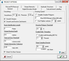
The General tab of the Project Options form includes a number of parameters including:
•Smoothing: CatchmentSIM 2.3 and above include smoothing of streams and subcatchments. The smoothness governs the number of bezier points used to approximate the curve, the precision refers to the maximum deviation (pixels) at points. The checkboxs govern whether to smooth stream, subcatchments or both.
•Drawing Speed: There are a number of options that can be tweaked to tailor display speed, however the defaults are recommended.
•Basin Identification Length: This integer value controls how CatchmentSIM determines the downstream subcatchment from a subcatchment outlet. CatchmentSIM determines the lowest elevation outlet pixel for a subcatchment and maps the downstream flow path from this point for the Basin Identification Length number of pixels. At this point, the subcatchment that the flow path is located within is determined to be the downstream subcatchment. This parameter may need to be adjusted higher if subcatchments with many outlet pixels are defined or lower if the catchment is discretised into many small subcatchments (of only a small number of pixels each) to ensure correct network topology.
•Stream Burning Depth: This decimal parameter governs how deep a stream will be burnt when the stream burning function is implemented (DEM Conditioning >> Burn Streams).
•Time Out Error Threshold: When using hydraulic controls such as gutters and channels, circular flow paths can be created which will crash CatchmentSIM if flow processing is initiated. To identify any problem areas, the Flow Mapping >> Map Pixel Flow Path tool can be used. This algorithm will inform the user of any invalid flow circles in the downslope flow path. This parameter is multiplied by #rows+#cols to ensure the parameters scales itself correctly. It shouldn't be necessary to adjust this parameter.
•Stream Intersection Tolerance: When the watercourse interpolation algorithm is applied (Create DEM >> Interpolation Tools >> Interpolate elevations along streams) CatchmentSIM analyses all intersections in the imported stream network to piece together the stream network and process watercourses in order of decreasing significance. This parameter defines how close together stream lines need to terminate (in terms of square root of easting deviation squared plus northing deviation squared) to be considered to join. This parameter may need to be adjusted up if the stream network has been manually digitised and intersections have not been 'snapped'. However, setting this parameter too high will cause false junctions, circular flow paths and may cause errors.
•Simplify Complex Polygons: If checked, CatchmentSIM will not attempt to increase speed by simplifying complex polygons. This is achieved by not drawing islands in multi-polygon polygons. Due to an improved complex polygon drawing algorithm introduced in CatchmentSIM 1.25, it should generally not be necessary to use this option.
•Dissolve Polygon Threshold: When exporting polygons from CatchmentSIM to external GIS applications (e.g., subcatchment boundaries), CatchmentSIM provides an option to dissolve small polygons (i.e., merge small polygons into a larger polygon that surrounds most of its sides). The Dissolve Polygon Threshold specifies the area of the small polygon as a percentage relative to the area of the larger polygon. If the dissolve small polygons export option is selected, all polygons smaller than X% will be dissolved (i.e., merged).
•Enable Multi Threading: If checked, CatchmentSIM will apply multi-thread processing to the flow processing and DEM interpolation algorithms. Multi threading enables CatchmentSIM to perform several tasks simultaneously, thereby providing an increase in computation speed. The number of tasks or "threads" that can be performed simultaneously are specified by the "Thread" number listed below the check box. Preliminary testing has shown that multi threading can double the speed of the flow processing and DEM interpolation algorithms on dual-core PCs. Multi threading is only suitable for PCs with multiple CPUs or CPUs with multiple cores. Care should be taken when applying this option as it is only in the Beta phase of testing.
•Slope Sampling Density: The number of points on the perimeter of a subcatchment to be used in the calculation of average vectored slope and hill slope calculations.
•min slope: The minimum slope possible for any of the slope parameters within CatchmentSIM. This ensures that all slope parameters are positive, and ensures that the impact of smoothing (which can sometimes cause negative slopes) is negated.
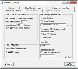
The Flat and Pit Removal tab of the Project Options form includes parameters for CatchmentSIM's two methods of flat and pit removal, namely the Filling Algorithm and breaching algorithm. These parameters include:
•Auto Flats and Pit Removal: This parameter specifies the criteria used to terminate the filling algorithm that is implemented as part of the Auto Flat and Pit Removal tool.
•Pixel Filling Increment: This parameter indicates the elevation added to flat pixels in each iteration of the filling algorithm. For more information see DEM Conditioning >> Filling Algorithm.
•Minimum Gradient: This parameter governs the minimum gradient that must be observed over the breaching solution channel before the algorithm will determine that a solution has been found. This parameter can be adjusted to ensure legitimate breaching solutions are found and that rounding errors do not cause breaching solution channels to become flat. For example, if the breaching minimum gradient is too low then a very shallow slope may be calculated over the breaching channel. After linear interpolation is applied to determine pixel elevation over the channel, these elevation will be rounded to the precision of the DEM (single or double). This can cause these pixels to become flat. More information regarding the breaching algorithm and adjustment of its parameters is shown in the Algorithm Section and the Key Challenges section.
CatchmentSIM 1.25 includes the option to auto-calculate the Minimum Gradient. This algorithm aims to determine the minimum downslope gradient that can be adopted before rounding errors will become a problem. If it is necessary for you to specify the breaching Minimum Gradient then uncheck this box and enter the required value.
•Treatment of Boundaries and Non-Defined Pixels: This parameter instructs the breaching algorithm what to do if a potential solution channel encounters a DEM boundary or blank pixel. Either the algorithm will terminate (the pit or flat will remain) or the algorithm will continue to search ignoring the boundary or blank pixel. The default option is to terminate the algorithm as ignoring the pixel can slow down the algorithm considerable and may also find solution channels that are not realistic (ie., in reality the flow path from the flat or pit pixel may actually flow across the DEM boundary). In practise, the flat and pit pixel near the boundaries should not be in the catchment of interest anyway. More information regarding the breaching algorithm and adjustment of its parameters is shown in the Algorithm Section and the Key Challengessection.
•Break Size: This parameter has been introduced for speed reasons, once the breaching algorithm has grown very large looking for a potential solution channel over a wide area it can slow down considerably. Once the breaching algorithm has grown to the Break Size the algorithm will terminate. If time is not a constraint this parameter can be adjusted upward to ensure the breaching algorithm finds even the most complex solutions.
•Max Elevation Gain: This parameter specifies the maximum elevation change that is permitted as part of the breaching algorithm. If the breaching algorithm finds a solution that requires the pixel elevations to be adjusted by more than the Maximum Elevation Gain in order to find a downslope flow path, this solution will not be adopted. This options helps to ensure that the source DEM will not be modified excessively as a result of the breaching algorithm. If the "Use Max Elevation Gain" check box is not selected, the breaching algorithm will attempt to find an optimal solution irrespective of the magnitude of elevation changes that may need to be accommodated across the DEM.
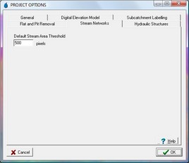
The Stream Networks tab of the Project Options form contains the following parameters:
•Stream Area Threshold: This parameter defines the default number of pixels that must drain to a single pixel before that pixel is considered a channel head. However, the stream area threshold for stream generation can be modified on activation of the Draw Streams function (Flow Mapping >> Generate Streams).
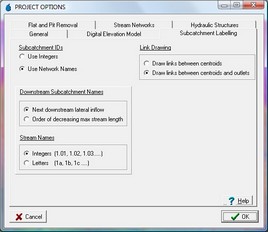
The Subcatchment labelling tab of the Project Options form governs how CatchmentSIM labels subcatchments in the Nodal Link Arrangement and consists of the following parameters:
•Subcatchment Identifiers: This option determines whether subcatchments will be labelled in a specific manner or simply with their internal integer code (i.e., the order in which they were defined).
The basic CatchmentSIM labelling system starts by identifying the main stream by flow length and will number subcatchments along this stream as 1.01, 1.02 etc in a downstream direction until reaching the catchment outlet. Subcatchment 2.01 will be at the head of either the next downstream lateral inflow tributary or the head of the second longest stream depending on the option selected in the Downstream Subcatchment Names option.
•Stream Names: This option determines if the subcatchments will be named numerically 1.01, 1.02 etc or by letters, 1a, 1b etc.
•Link Drawing: This option determines whether links will be draw between subcatchment centroids and their outlet and then to the downstream subcatchment centroid or simply between subcatchment centroids and the next downstream subcatchment centroid.
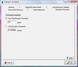
The Hydraulic Structures tab of the Project Options form includes parameters designed to control the operation of Hydraulic Controls within CatchmentSIM, specifically:
•HC Breach Sensitivity: This option governs how hydraulic breaches will be determined. They can either be derived by a distance measure (pixel number threshold) or an elevation tolerance. In the case of a distance measure, if a pixel of lower elevation can not be found along the gutter within the pixel tolerance then a hydraulic breach is formed and the flow path overtops the gutter. In the case of an elevation tolerance, if a pixel of lower elevation can not be found along the gutter without gaining more than the elevation tolerance (over the flow path along the gutter to get to the lower elevation pixel) then a hydraulic breach is formed and the flow path will overtop the gutter. This is designed to simulate ponding behind a gutter and eventual overtopping. More information of Hydraulic Controls and breaches can be found in the Algorithm Section, the Key Challenges Section and the Hydraulic Controls form.
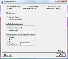
The Digital Elevation Model tab of the Project Options form contains parameters related to the DEM created by CatchmentSIM, specifically:
•DEM Precision: The DEM precision parameter governs whether the DEM will be stored as single or double precision floating point values. Single precision stores 7-8 digits while double precision stores 15-16 digits. Selecting double precision will double the DEM file size, increase total project files by around 20% and runtimes by 20% as well as RAM requirements. Double precision may be required when using elevation data with several digits on the left side of the decimal point such as 10450.056 ft, in very flat DEMs or if you wish to use a low breaching minimum gradient parameter.
•Vector to Raster Conversion: This parameter governs wether all pixel underlying an imported contour will be assigned the contour elevation or only those identified by the selective vector to raster conversion algorithm. This algorithm is described in the Algorithm Section. It is generally accepted that selective assignment of underlying pixels creates more realistic DEMs and thus, this is the default option.
•Multiple Contours Option: This option governs what elevation will be assigned to pixels which underlie multiple contours with differing elevations. The options are average value (default), max, min or a max/min threshold. The max/min threshold option is designed to ensure that the extremities in the DEM are represented by picking the maximum contour elevation if the average value is greater than a threshold value and the minimum contour elevation in the average value is less than the threshold.
