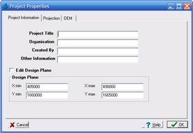
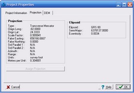
The Project Properties form displays general CatchmentSIM project information, information on the current coordinate projection and the details of the project DEM. The form also allows the general project information, design plane extents and projection (if none is specified) to be modified.
Project Information
Project Information (e.g., Project Title, Organization etc) for the current project is listed at the top of the Project Information Tab. This information can be modified by replacing the existing text within the text boxes.
The "Design Plane" section of the Project information tab displays the design plane extents of the current CatchmentSIM project. The design plane extents can be modified by selecting the "Edit Design Plane" check box and entering the appropriate X and Y coordinate values in the text boxes. This option can be used, for example, if it is determined that the project design plane is not sufficiently large to fully contain all of a catchment. However, please be aware that modifying the design plane will delete the current CatchmentSIM DEM. Therefore, it will be necessary to setup a new DEM for the project and undertake hydrologic conditioning, subcatchment delineation etc. Therefore, it is typically more efficient to initially overestimate the design plane extent and apply a clip mask to reduce the extent of the DEM if necessary.
Projection
The Projection tab lists the attributes of the projection defined for the CatchmentSIM project. The project projection is established based on selection of a specified projection class and subclass in the New Project form or by using the Custom Projection form.
If no projection is assigned to the CatchmentSIM project, the projection can be specified by selecting the "Assign Projection" button.
DEM
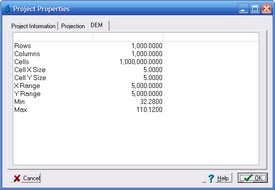
The DEM tab provides information on the CatchmentSIM DEM (if one has been developed). The information provided includes:
•Rows: The number of rows in the current DEM.
•Columns: The number of columns in the current DEM.
•Cells: Number of cells (pixels) in the current DEM. This is calculated by multiplying the number of rows by the number of columns.
•Cell X Size: The size of each DEM cell in the X direction.
•Cell Y Size: The size of each DEM cell in the Y direction.
•X Range: The size of the total DEM in the X direction. This is calculated by multiplying the number of Columns by the Cell X Size.
•Y Range: The size of the total DEM in the Y direction. This is calculated by multiplying the number of Rows by the Cell Y Size.
•Min: Minimum DEM elevation.
•Max: Maximum DEM elevation.


