CatchmentSIM includes a range of tools designed to accommodate representation of urban areas in a project. Firstly, CatchmentSIM allows calculation of impervious area proportions for subcatchments (GIS >> Impervious Areas) which is a parameter required for almost all hydrologic models. Furthermore, CatchmentSIM offers a more comprehensive method of urban analysis. Realistic modelling of runoff in urban areas requires consideration of the numerous processes that may be in play during a rainfall event in an urbanised catchment. These processes may include roof, downpipe, fencing, roads, footpaths, gutters and piped drainage systems (Goyen and O'Loughlin 1999). CatchmentSIM accommodates individual representation of several of these processes by modelling individual flow path deviations occurring as a result of urban hydraulic controls (Flow Mapping >> Database) such as roads, gutters and channels networks.
Impervious Area Database
CatchmentSIM provides capability for a database of impervious areas to be maintained within each project (GIS >> Impervious Area). This database can be constructed by drawing impervious area polygons on the screen or importing them from external GIS databases. These polygons can each have a description, percentage impervious and on / off state. Users can simply turn individual polygon on or off, alter their attributes or group select and manipulate them based on particular attributes (such as selecting all polygons labelled as 'Road'). An example of the impervious area database is shown in Figure 29.
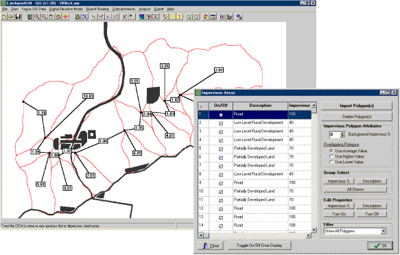
Figure 29 : Impervious Areas Database
CatchmentSIM can accommodate complex polygons such as concave or convex polygons, or multi-region (island) polygons. An example of an island polygon is provided in Figure 30 as well as in Figure 29 (closest to the 1.06 subcatchment label). CatchmentSIM will automatically calculate impervious percentages for each subcatchment based on the impervious area polygons, their individual impervious proportions, and the background impervious proportion. The background impervious proportion is an impervious proportion that is applied to all areas outside of the impervious area polygons. This value is designed to represent sporadic impervious areas such as rocky outcrops and may be set at any value between 0 and 100%. CatchmentSIM calculates impervious areas by determining which DEM pixels are within impervious area polygons and tallying their area multiplied by the impervious proportion assigned to the impervious area polygon. The algorithm CatchmentSIM utilises to determine if a DEM pixel is within a polygon is based on constructing a horizontal line in one direction from the centroid of the DEM pixel and counting the number of intersections with the polygon boundary. An odd number of intersections indicates that the DEM pixel is within the polygon whereas 0 or an even number of intersections indicates that the DEM pixel is outside the polygon boundary (or inside an island).
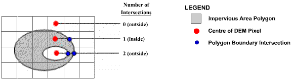
Figure 30 : Rasterisation of Impervious Area Polygons
Modelling of Hydraulic Structures
CatchmentSIM includes a number of tools to help model flow paths in urban environments. Urban structures have a significant effect on flow paths in urban areas and they are usually not represented in source GIS data such as DEMs or contour and stream alignments. As such, they need to be added into a CatchmentSIM project as an addition to the source GIS data. This can be achieved by one of two approaches. Firstly, the urban structures can be hard-coded into the DEM by changing the elevations of relevant DEM pixels to cause flow paths to act in a realistic manner in the vicinity of urban structures. Alternatively, urban structures can be modelled in CatchmentSIM as supplementary objects that control flow paths when they intersect the alignment of an urban structure. Modelling urban structures in this way does not require the DEM pixel elevations to be altered. Furthermore, each individual urban control can be turned on or off, and flow paths and subcatchment layouts may be regenerated easily. This is valuable when analysing drainage studies for hydrologic events of differing magnitudes where particular urban structures may only be relevant for certain storm magnitudes, or during flood mitigation scenario analysis.
CatchmentSIM accommodates both of these modelling approaches. An example of hard-coding urban structures into the DEM is presented in Figure 31, where road crown alignments were hard-coded into DEM by raising all pixels along the road crowns by 0.5 metres using CatchmentSIM's vector dataset operations (DEM Conditioning >> Vector Dataset Operations). The breaching algorithm was then applied to remove resultant flat and pit pixels and breach the road crowns at their points of lowest elevation.
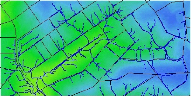
Figure 31 : Effect of Hard-Coding of Road Crowns on Stream Network
As shown in Figure 31, the calculated stream network has been strongly affected by the hard-coding of urban structures.
Alternatively, urban structures can be modelled separately using CatchmentSIM's hydraulic control tools. These tools allow representation of channels and gutters in a CatchmentSIM project that act as overriding flow controls. These hydraulic controls are described in the following sections.
Channel Type Hydraulic Controls
Channel type hydraulic controls (Flow Mapping >> Create Controls >> Draw Channel) are drawn in CatchmentSIM as a solid line with triangles pointing towards the channel outlet  and by one of the following symbols in the Hydraulic Controls Form -
 or
or  . These controls have the effect of forcing flow paths that intersect with these controls to follow the channel until its outlet point regardless of whether this involves upstream flow, or flow in a direction that does not represent the steepest downslope direction at that point in the DEM. These hydraulic controls should be used when a user wishes to completely override the DEM and force flow to follow a pre-determined path. Channel type hydraulic controls should be used to represent drainage channels or urban flow paths that are not represented in the DEM or source contour data. A stream network can also be imported as channel type hydraulic controls to force flow to follow an existing stream network as shown in Figure 32.
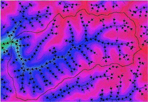
Figure 32 : Using a Stream Network as Channel Hydraulic Controls
Gutter Type Hydraulic Controls
Gutter type hydraulic controls (Flow Mapping >>Create Controls >> Draw Gutter) are drawn in CatchmentSIM as a solid line with triangles pointing perpendicular to the direction of the line  and by one of the following symbols in the Hydraulic Controls form
  or
or  . The triangles point in the direction in which flow is allowed to pass over the hydraulic control.
When a flow path intersects a gutter type hydraulic control, flow will still follow the DEM calculated steepest descent within the restrictions imposed on the flow direction by the gutter. If the flow direction would see the flow path crossing the gutter (against the direction of the arrows) then it is restricted from doing so. Instead, flow is allowed to travel along the gutter provided this direction represents a downslope gradient. If neither of the along-gutter directions are downslope then the flow path is trapped. The gutter processing algorithm will then search along the gutter in both directions within a specified tolerance for a pixel of lower elevation. If such a pixel is found within the tolerance then the flow path will be mapped to this point, and the algorithm is re-applied at the new location. The tolerance may be in the form of a set number of pixels or a set elevation. The effect of this algorithm is to simulate ponding at low points behind gutters which would in reality fill the pixel elevation and allow flow to progress to pixels of higher elevation provided they are lower than the height of the gutter. The gutter height is simulated in CatchmentSIM by utilising an elevation tolerance (CatchmentSIM Drop Down >> Project Options | Hydraulic Structures). If a pixel of lower elevation is not found within the specified tolerance then a hydraulic breach is formed and the flow path is permitted to breach the gutter. This can be seen in Figure 33 where flow paths travel along the gutter until the searching algorithm fails to find a suitable downslope pixel along the structure and a hydraulic breach occurs.
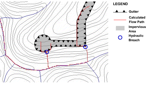
Figure 33 : Hydraulic Representation of Gutters