CatchmentSIM allows for the natural flow paths derived from the DEM to be overridden by adding vector Hydraulic Controls to the project as outlined in the algorithm section. This section aims to demonstrate the basic principles of their operation.
Channel Type Hydraulic Controls
Channel type hydraulic controls (Flow Mapping >> Create Controls >> Draw Channel) are drawn in CatchmentSIM as a solid line with triangles pointing in the direction of the line towards the channel outlet  and by one of the following symbols in the Hydraulic Controls Form
  or
or  . Channel hydraulic controls force flow paths to follow the channel regardless of the underlying topography. Figure 43 illustrates how a channel type hydraulic control affects flow paths from nearby pixels. Figure 44 illustrates the effect on subcatchment mapping of the same channel hydraulic control.
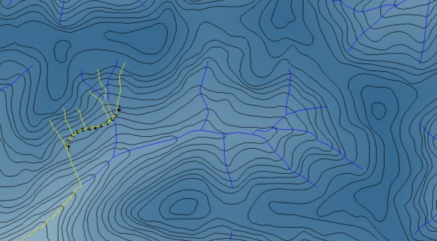
Figure 43: Channel Hydraulic Control Flow Paths
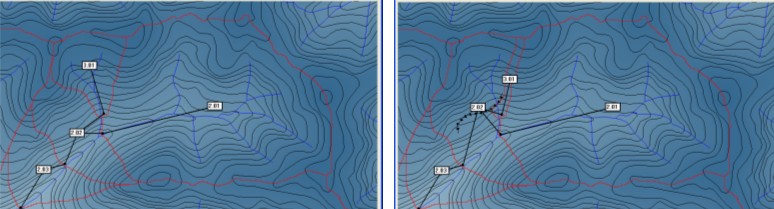
Figure 44: Subcatchments Mapped with/without Channel HC
It is necessary to be careful when placing channel type hydraulic controls. If placed incorrectly, they can cause infinite flow loops, such as the example depicted in Figure 45. This flow from the end of this channel will drain back into the channel creating a perpetual flow path. CatchmentSIM attempts to diagnose these problems but it is prudent to test hydraulic control by manually mapping flow paths (Flow Mapping >> Map Pixel Flow Path) in the vicinity of the hydraulic control and checking for Timeout Errors (which indicate a Hydraulic Control problem).
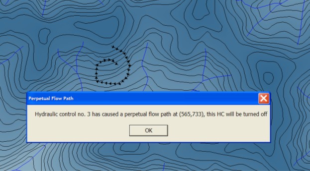
Figure 45: Perpetual Flow Path Example
Gutter Type Hydraulic Controls
Gutter type hydraulic controls (Flow Mapping >> Create Controls >> Draw Gutter) are drawn in CatchmentSIM as a solid line with triangles pointing at a perpendicular angle to the direction of the line  and by one of the following symbols in the Hydraulic Controls form
  or
or  . The triangles point in the direction in which flow is allowed to pass over the hydraulic control. When a flow path intersects a gutter it is only permitted to cross the gutter in the direction of the arrows, otherwise it must flow along the gutter in a downslope direction. The exception occurs when a downslope direction can not be found. In this case, the algorithm will search within a given tolerance, either a number of pixels or a given elevation (CatchmentSIM Drop Down >> Project Options | Hydraulic Structures) for a pixel of lower elevation. If one can be found within the tolerance, then flow is mapped to this point, if not then a hydraulic breach occurs. Figure 46 and Figure 47 illustrate the flow paths mapped from the same points using gutter hydraulic control with two different elevations based hydraulic breach tolerances (0.15m in the first figure and 0.30m in the second figure).
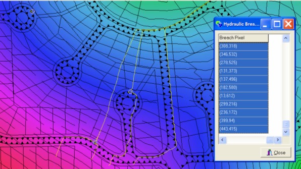
Figure 46: Effect of Gutter HC with Low Tolerance
Figure 46 shows that many hydraulic breaches are formed (yellow circles - Flow Mapping >> View Breach Locations) where the gutter hydraulic control is breached. This is designed to simulate ponding behind the low elevation gutter and indicate the points at which it will breach. However in Figure 47 where a higher gutter is implemented (using a higher elevation tolerance in the Project Options form), that fewer hydraulic breaches are formed and a significant change in the mapped flow paths is evident. Thus the elevation tolerance of the gutter type hydraulic controls can have a significant effect on flow paths and subsequent subcatchment mapping.
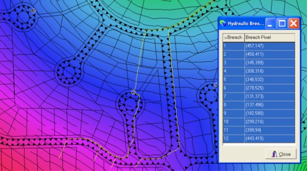
Figure 47: Effect of Gutter HC with high tolerance