There are various settings available on the Settings tab. The Settings can be saved for use as future defaults using the 'Save Default Settings' button.
Most settings are self explanatory, however, the more important ones are:
General Settings

Event Naming
There are various options for how events (and their associated result files) will be named, including:
•Removing sapces from the Event ID
This option ensures spaces are not included in output files (default is selected).
•Include the Classification in the Event ID
This will include the frequent, rare and intermediate classifications in the Event ID. This will have the effect of treating patterns drawn from different bins as being different ensembles. For example, with this setting turned off (the default), if both the frequent and intermediate bins are used for the 10% AEP event, a 20 storm ensemble will be analysed versus two different events of 10 storms. This is further discussed in Using Temporal Patterns from Multiple Bins.
•label with TP 1..10 instead of TP ID
By default, output files have the Data Hub defined temporal pattern ID appended to the end of their filename. This option will instead append TP1 through to TP10 (or higher for larger ensembles) to output files. This can be useful for creating ts1 export files for TUFLOW with a standardised naming format. If this option is selected, you will also see the TP1 tags shown in result and chart views.
•Replace '%' with 'pc'
This may be required if downstream software does not work well with '%' signs in event names and file names.
Other important general settings are:
•Very Short Duration Events
No temporal patterns are included in the ARR Data Hub for durations of 5 mins or shorter. If this checkbox is selected then Storm Injector will create storms with 1 timestep equal to the duration and deposit 100% of the rainfall depth in that timestep.
•Pause between model runs
For hydraulic models that require hardware dongles to run (particularly network dongles), it may be necessary to insert a pause between model runs.
•Downloading from Web
The Show Browser checkbox determines if the web browser will wait for the user to click Ingest Data before processing the data or if it will process automatically. The loading time governs how long the program should wait before trying to read the data. If downloading data is causing errors or you have a slow connection, you should try entering a larger loading time. You can also access the legacy and development versions of the Data Hub from this setting.
•Multi-Core Processing
Some intensive analysis (such as at-site IFD analysis) allow multi-core processing, this value specifies how many cores will be used and is set by default based on the number available in the PC minus 2.
•Data Hub Version
By default, Storm Injector will download Data Hub information (Step 2) from the ARR Data Hub, however, the development and 'legacy' versions of the Data Hub can be accessed by changing this field.
•Browser Version
By default, Storm Injector will use the Internet Explorer that is embedded in windows. However, to improve speed, compatibility with different resolutions or satisfy security concerns, the Browser may be changed. The Edge Browser is more modern but does require the 'WebView2Loader.dll' file to be present and for Edge to be installed. It may also create a 'Storm_Injector_HL.exe.WebView2' folder when run. The Indy Direct browser does not require any files and is very fast but it does not display the webpage, the data is ingested automatically.
•Region
The region setting may be changed to NZ to customise the software for New Zealand users.
Hydrologic Model Paths
Users will need to enter the path of the hydrologic engine they would like to use.
RAFTS
In the case of XP-RAFTS, this file is called 'raftsEngW.exe'.
Also ensure that the Job Control and individual nodes are setup to export total hydrograph files (*.tot) to allow plotting of hydrographs in the software.
WBNM
In the case of WBNM, it is suggested that the new slim engine is utilised. This file may be called: file wbnm_eng_w64.exe
Also ensure that WBNM is setup to export metafiles to allow hydrograph export (out_metafile=.TRUE. to allow hydrographs)
RORB
In the case of RORB, please select the command line version of the engine. This may be called RORB_CMD.exe
URBS
In the case of URBS, please select the urbs32.exe file.
HEC-HMS
HEC-HMS requires two software to be installed on the client PC, DSSVue (v3.2 +) and HEC-HMS (v4.8 +). Some links to supported versions are:
DSSVue: https://www.hec.usace.army.mil/software/hec-dssvue/downloads/HEC-DSSVue_323_Setup.exe
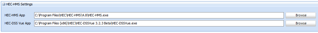
Once, these software are installed, please ensure the paths to the relevant exes are listed in the Settings tab and then click Save Default Settings
Initial and Continuing Loss
There are numerous methods available to calculate the burst losses for a storm. These include using the global initial loss from the ARR Data Hub and subtracting the corresponding pre-burst depth. The user may also choose to apply the ARF to pre-burst depths prior to their subtraction from the initial loss.
Various other methods are also available including Rahman et al. 2002 and Hill et al, (1996, 1998). Probability Neutral Burst Initial Losses are available if the Data Hub provides them for the area (typically NSW). Calibrated initial loss values can also be adjusted to Burst Losses using the formula described in the NSW specific advice page on the Data Hub.
The initial and continuing loss rates can also be overridden if required (refer to the next section). Pre-burst subtractions are still made to the Override Initial Loss if selected.
Urban losses can also be calculated based on classifying some or all of the non-impervious parts of subcatchments as Indirectly Connected Areas (ICAs). This is discussed further in the How To section's Guide to Urban Loss Rates.
Impervious loss rates are also assigned in these settings.
The user can also nominate to apply any excess pre-burst to the first timestep using the pre-burst excess options.
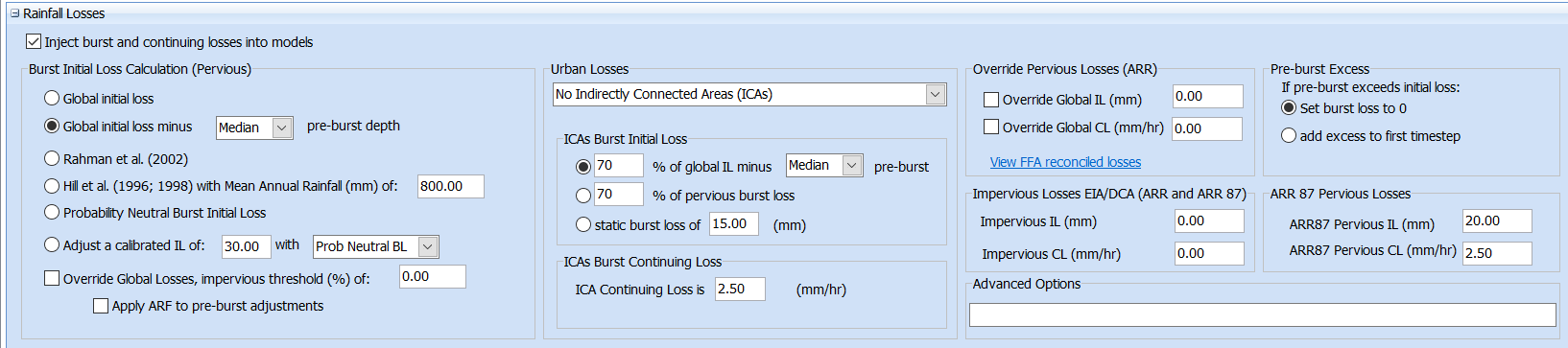
Storm Injector also includes an option to apply advanced loss models in the Advanced Options settings. These include:
•The Probabilistic Proportional Loss Model
This loss model allows the proportion of rainfall lost for each timestep to be defined by a factor which is determined from a lookup table based on cumulative rainfall. Furthermore, an intensity threshold can be defined (mm/hr), over which a separate runoff coefficient (the inverse of the loss factor) can be applied. Before applying this model, Ensure the Burst Initial Loss Calculation Section is set to Global Initial Loss and the Global IL and CL are checked to override and set to 0.
An example of applying this model would be entering the following text in the Advanced Options box: CustomRainfallLoss_PPL_RC(20,"0,62.5,125,250","0.955,0.94,0.925,0.9",25,0.3)
This can be decoded as:
•Initial Loss of 20mm
•X Values (Cumulative Rainfall) in PPL lookup table are: "0,62.5,125,250" And Y Values (loss proportion) are: "0.955,0.94,0.925,0.9"
•Intensity Threshold is 25 mm/hr. The Intensity Theshold option can be omitted by setting this as a high value such as 9999.
•Runoff coefficient is 0.3 (ie., 70% of rainfall will be lost in timesteps where intensity exceeds 25 mm/hr)
Customised initial and continuing loss
For advanced use, loss rates can be uniquely assigned for any AEP or subcatchment using the 'Override Global Losses' option. When this check box is selected, you will see a new panel on the Storm Generator tab that allows losses to be entered in a flexible manner. The Storm Burst Losses panel will disappear since loss rates may now vary with subcatchment.
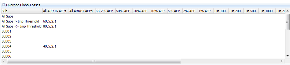
Unique initial losses (mm), continuing loss (mm/hr), impervious initial loss (mm) and continuing impervious loss (mm/hr) can be entered in any cell using 4 comma seperated values For example: 80,5,1,0.
A hierarchy is applied to determine the loss rates to use for each subcatchment when preparing the storm files.
1.If loss rates are entered for the specific subcatchment row and specific AEP column, these are used, otherwise:
2.If loss rates are entered for the specific subcatchment row and the relevant all AEPs column (All ARR16 AEPs or All ARR87 AEPs), these are used, otherwise:
3.If loss rates are entered for the relevant impervious threshold row (based on the impervious threshold in the settings and the subcatchment impervious proportion) and the specific AEP column, these are used, otherwise:
4.If loss rates are entered for the relevant impervious threshold row (based on the impervious threshold in the settings and the subcatchment impervious proportion) and the relevant all AEPs column (All ARR16 AEPs or All ARR87 AEPs), these are used, otherwise:
5.If loss rates are entered for the 'All Subs' row and the specific AEP column, these are used, otherwise:
6.If loss rates are entered for the 'All Subs' row and the relevant all AEPs column (All ARR16 AEPs or All ARR87 AEPs), these are used.
For example, in the image shown above subcatchments with more than 0% impervious will be assigned 60 mm IL and 5 mm/hr CL where subcatchments with 0% impervious are assigned 80 mm IL and 5 mm/hr CL. The exception is Sub04 which is assigned 40 mm IL and 5 mm/hr CL. This can be further customised for individual AEPs if needed. The impervious proportion threshold used can be set in the Settings.
You can right click on this form to import and export to CSV. If you wish to work in Excel, it is recommended that you export to CSV as a first step, then edit as required in Excel and then import from CSV.
In the case of RORB, Interstation Areas are used for loss rate customisation instead of subcatchments. Also, the impervious proportion options are not available for RORB.
You should note that adjustments to these loss rate can still be made including subtraction of pre-burst depths or percentage reductions in initial loss. If you wish the loss rates in the Override Global Losses panel to be used without modification, ensure the 'Global Initial Loss' radio button is selected in the Initial Loss group box and the 'Adjust initial loss by' checkbox is not checked.
This method of customising initial and continuing loss rates is considered suitable for advanced users. It is more difficult to check the correct allocation of the loss rates since the initial and continuing loss columns in the Storms grid will now show 'override' instead of values since these values may now vary by subcatchment. Users should check the hydrologic model files generated by the 'Prepare Model Runs' step and confirm that the loss rates are correct.
Temporal Pattern Settings
Users may choose how a adopted temporal pattern for a given duration and subcatchment is selected. The options are shown below:
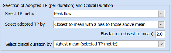
•Select TP Metric
This option identifies which metric will be used for selection of the adopted TP. The default is peak flow but volume and time to peak may also be selected (for example for volume sensitive catchments or emergency management considerations).
•Select adopted TP by
This option identifies how the adopted TP is selected from the temporal patterns in the ensemble. The default it to select the closest to the mean with a bias (default of 2) to those above the mean. For example, a bias factor of 2 would mean that a temporal pattern yielding a peak flow less than the mean would need to be half the 'distance' to the mean that the nearest result exceeding the mean before it would be selected. Other options for selection of the adoopted TP include the first exceeding the median (or median if odd number of patterns) or the first exceeding mean.
•Select critical duration by
This option identifies which duration is selected as the critical duration. The default is to use the highest mean of the temporal pattern metric (normally peak flow). However, in some circumstances, the adopted TP for the critical duration can be lower than the adopted TP for other durations. As such, there are also options to use the highest adopted TP to determine the critical duration, or the highest of the mean or adopted TP. The default is to use the selected TP metric as the basis for the critical duration but you can also explicitly instruct Storm Injector to use peak flow, volume or time to peak for the critical duration. For example, you may wish to use Time to Peak as the basis for your selection of the adopted TP but still select the critical duration based on mean ensemble peak flow. There is also an option to use minimum Time to Peak for determining critical duration.
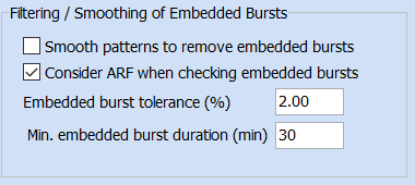
Users can also choose how to handle embedded bursts within storms. Embedded bursts are detected based on analysis of the IFD depth, Areal Reduction Factor (ARF) and temporal patterns and can be smoothed by iteratively bringing all non-zero timesteps in the pattern towards the mean (i.e., higher rainfall depths are deduced and lower rainfall depths are increased) until the burst is removed. A more details 'how to' guide for embedded bursts can be found here.
Other factors that should be kept in mind regarding embedded bursts are:
•Rainfall increases in custom and climate change events are not considered for embedded bursts.
•Injection of pre-burst rainfall are not considered for embedded bursts.
•Only bursts with durations that divide evenly into the storm timestep are considered when checking a temporal pattern for an embedded burst.
•A minimum duration can be set for which embedded bursts will be search for and smoothed (if this option is selected). For example, in a large catchments, you may not want to consider embedded bursts less than several hours. Using care when considering this setting can help avoid over-smoothing of rainfall hyetographs.
Custom Pre-Burst Temporal Patterns
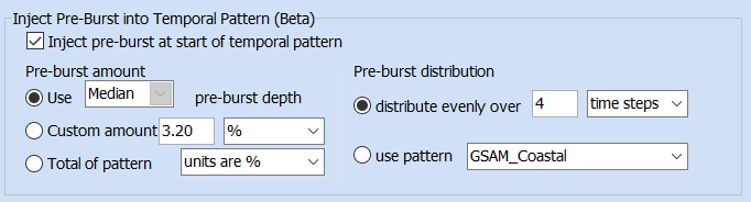
From Storm Injector 1.2.5, pre-burst rainfall can be distributed over a number of time increments at the start of a simulation according to a pre-burst temporal pattern or evenly distributed. There are a number of options for selection of the amount of the pre-burst and how it is distributed in the 'Inject Pre-Burst into Temporal Pattern' options in the Temporal Patterns panel. There is more detail on the use of this feature in the Using Pre-Burst Temporal Patterns section.
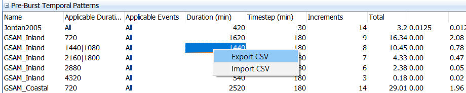
The custom pre-burst temporal patterns that can be used in the software are listed in the Pre-Burst Temporal Patterns panel. This database can be exported to CSV, edited and re-imported, or edited directly within the interface.
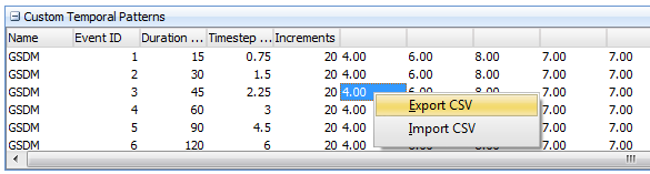
Custom Temporal Patterns
Storm Injector allows custom temporal patterns to be input by users to apply specialised methods. The GSDM temporal pattern for the PMF is included in the section by default but others can be added. These may include specialist PMF methods such as GSAM. The easiest way to add custom temporal patterns is to right click and export to CSV. This CSV can then be edited in Excel, saved and re-imported into Storm Injector. These temporal pattern can be applied using the procedures documented in the Custom Events section.
Very Short Duration Events
For storm of durations of 1-5min, users may elect to have single timestep storms added or not using the 'Add single timestep events for 1 - 5 min checkbox.
At-Site IFD ANALYSIS

The At-Site IFD settings include settings used by the tools in the At-Site IFD tab. These include:
•The durations (mins) for which you wish to calculate annual maximum series of rainfall
•What proportion of a year must have data for it to be included in the annual maximum series
•The plotting position constant. ARR Book 3 Chapter 2, Section 2.6.2 suggests that a plotting position constant of 0.4 (termed the Cunnane 1978) should be used to maintain consistency.
•The Daily Restricted Conversion Factors (as per ARR Book 2, Chapter 3, Table 2.3.4).
Utilities
Various utilities can be linked via the Settings to help integrate Storm Injector with other products these include:
•convert_to_ts1.exe - This utility is used to convert hydrograph output files to ts1 format for TUFLOW