Selecting the 'Show Layer Control' menu item hides the View Controller if the View Controller is currently displayed, or displays the View Controller if the View Controller is hidden.
The View Controller, which is shown below, allows the user to customise the current display by selecting which layers are displayed, their attributes (colour, fill, transparency, line types etc), their display order and other properties (which may be dependent on the layer selected).

Display Order
The display order of vector and raster/grid layers can be modified by left clicking and dragging the required layer to the desired position in the layer list. The layer that is displayed at the top of the View Controller list will be displayed on top of all other layers. Conversely, a layer that is displayed at the bottom of the View Controller list will be displayed beneath all other layers.
Adding a Vector Layer
Vector layers will appear in the View Controller once they are available. For example, contours, streams and impervious areas will appear once they have been imported, basin outlets will appear once they have been defined (Subcatchments >> Draw Outlet), subcatchment boundaries, synthetic stream network will appear once they have been generated (Flow Mapping >> Generate Streams) and subcatchment boundaries will appear once they have been mapped. The Nodal Link Arrangement will appear when there is more than 1 subcatchment.
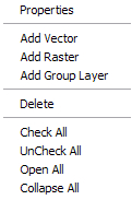
External vector (i.e., GIS) layers can also be added for display purposes by right clicking on the View Controller, which will display the View Controller pop-up menu (as shown below). To add an external vector layer select 'Add Vector' from the pop-up menu. The pop-up menu also allows you to access layer properties (this can also be completed by double clicking the layer), delete layers, add group layers, expand or collapse all layers, and check or uncheck all layers.
Vector layers can also be added by clicking the green + icon on the toolbar and selecting the layers to be added. Take care to ensure the drop down "Files of type" box is set to "All Supported Vector Files".
Nodal Link Arrangement Display Properties
The buttons and check boxes displayed on the View Controller may change according to the vector layer that is selected. For example, the Show Labels and Show IDs check boxes will only appear for the Nodal Link Arrangement layer. This option controls whether the default CatchmentSIM labels or user labels are displayed in the nodal network or simply lines (more options regarding the nodal link arrangement can be set in the Project Options form).
Synthetic Stream Network Display Properties
If vector streams have been generated (Flow Mapping >> Generate Streams) then the display of the Synthetic Stream Network may be selected in the View Controller. To edit the display properties for the Synthetic Stream Network, double click the layer to display the following form.
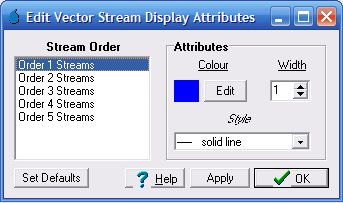
This form allows stream segments of differing Horton order to be displayed in a different colour, width and style.
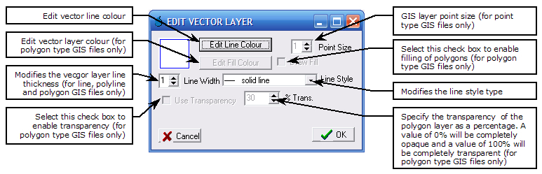
The display properties of each vector layer can be modified by double clicking any vector layer in the View Controller or by right clicking on the vector layer and selecting 'Properties' from the pop-up menu. This will display the Edit Vector Layer form which enables vector line types, colours, thickness, fill types and transparency values to be altered as shown below.
The subcatchment layer can be mapped thematically. This allows visualisation of any subcatchment attribute using a colour gradient.
To access, simply double click on the subcatchment layer and select the Thematic Mapping tab. Select the 'Apply Thematic Mapping' check box and then select the 'Configure Thematic Mapping' button. There are a number of options available for configuration of the thematic mapping. Firstly, select the attribute you wish to map (these are based on the columns configured for display in the Subcatchment Manager). Next, select if you want all unique values assigned a colour, or a certain number of equal ranges, or a certain number of unequal ranges (designed to have a similar number of subcatchments in each colour range). Select a default colour palette/gradient and then click the "Add" button. The list of categories should now be displayed. The colours assigned to individual categories can be altered in this list, if desired. Alternatively, select a new Gradient/fill from the top left drop down box and click "Re-Apply Gradient".
Adding a Raster, Grid Layer or Aerial Image
Raster layers (e.g., aerial/topographic images or grid layers) may be added to a project by right clicking on the View Controller and selecting 'Add Raster' from the pop-up menu, or by clicking the green + icon on the toolbar and selecting the layers to be added. Take care to ensure the drop down "Files of type" box is set to "Any Raster File (*.*)" or "Well Known Images" for aerial photography. Multiple Raster files can be selected and imported simultaneously (see "Raster/Grid Layer Multi-select" below).
Three options are available to automatically geo-reference images in CatchmentSIM. By default, CatchmentSIM will attempt to read any embedded coordinate projection information and use this to geo-reference the raster layer. If no projection information can be located or it can not be interpreted, the user may specify that the raster layer is in the same projection as the CatchmentSIM project or specify an alternative coordinate projection manually.
If no coordinate or geo-referencing information is embedded within the image, the image can be geo-referenced manually. There are two interactive methods for geo-referencing a raster image as well as three numerical standards for storing the geo-referencing data. At this stage, CatchmentSIM does not support rotation of manually geo-referenced images, thus, raster images must be aligned with the north/south, east/west axis of the adopted projection.
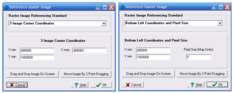
If the image boundary coordinates or pixel size is known then the image may be manually geo-referenced by typing the information in after selecting the appropriate referencing standard. If the coordinates of the image boundary are known then the 3 Point Image Corner Coordinates or the Known Lat/Long Coordinates standard can be used. However, if the bottom left coordinates and pixel size (in map units) are known then the Bottom Left Coordinates and Pixel Size standard can be used.
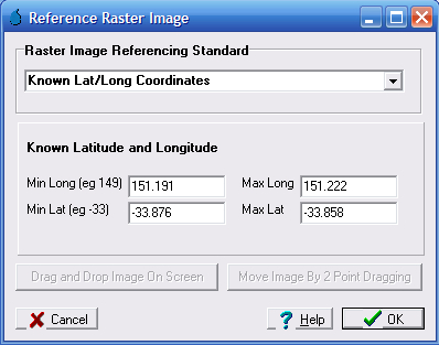
The Known Lat/Long Coordinates option is useful when geo-referencing an image exported from Google Earth. The coordinates can be extracted by running the curser over the corners of the image in Google Earth and noting the lat/long coordinates, which are displayed in the lower left hand corner of the screen. The lat/long coordinates can then be entered in the relevant sections of the Known Lat/Long Coordinates form.
If coordinate information is not known, the image may be geo-referenced visually. The Drag and Drop On Screen button will cause the form to disappear and then the user is requested to select the diagonal corners of the images location by reference to the displayed map information. A rectangle will be drawn as the cursor is moved (after input of the first point) to help visualise the image location. Once the second point has been added, the form will reappear and the relevant coordinate information is added. At this stage the Move Image By 2 Point Dragging option may be used to fine tune the image location. This option allows the image to be re-scaled by associating two known points on the image with their real locations. After clicking the button, the form will disappear. First click a point on the image and then click it's proper location, after repeating this twice, the image will be automatically rescaled, the form will reappear and coordinate information will have been updated.
| Note: | The Drag and Drop On Screen option must be used before the Move Image By 2 Point Dragging option can be used. |
The DEM will appear in the Raster Layers checklist box once it has been setup (Create DEM >> Setup Blank DEM).
External raster layers can also be added for display purposes by right clicking on the View Controller and selecting 'Add Raster' from the pop-up menu.
CatchmentSIM currently supports the display of the following Image file formats:
•ADGR/ARC Digitized Raster Graphic
•Windows Bitmap (*.bmp).
•ERMapper Compressed Wavelets (*.ecw).
•USGS DOQ (*.doq)
•Intergraph Raster
•IRDAS Imagine (*.img)
•IDRISI Raster
•Graphics Interchange Format (*.gif).
•TIFF and GeoTiff (*.tiff).
•JPEG (*.jpg).
•JPEG 2000 (*.jp2, *.j2k).
•MrSID (*.sid).
•Portable Network Graphics (*.png).
•SGI Image Format (*.sgi)
•Windows Metafile (*.wmf).
Raster Layer Display Properties
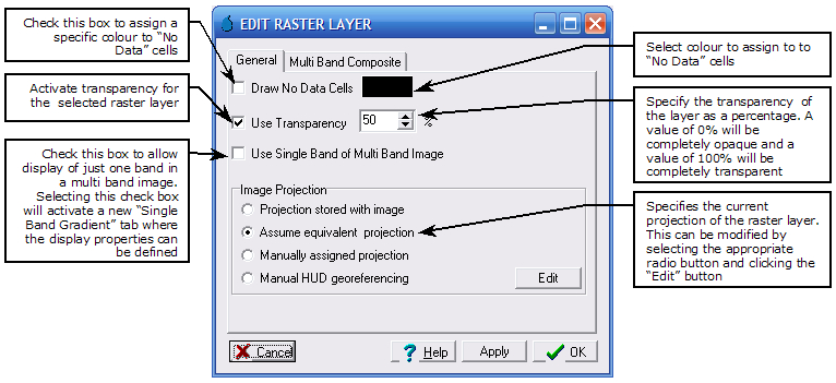
Once a raster layer is added to the CatchmentSIM project and assigned an appropriate projection, the display properties of the layer can be modified by double clicking the raster layer or by right-clicking the raster layer and selecting Properties from the pop-up menu. Please note that not all of the options shown on the General tab below will be available for all raster layers. Further detailed display options are available on either the "Multi Band Composite" tab or the "Single Band Gradient" tab (refer Raster / Grid Layer Display Options below).
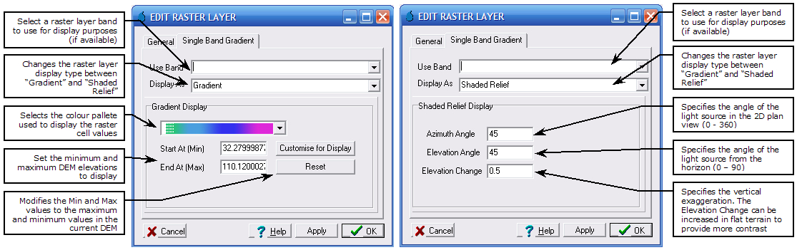
Raster/Grid Layer Display Options
There are a number of options regarding how the DEM and grid layers are displayed. They may be displayed using a variety of colour gradients and the maximum/minimum display elevations may be adjusted. The DEM may also be displayed as a Shaded Relief (i.e., hillshade) diagram. The Shaded Relief display option adds a light source to the display. This provides a faux 3D effect without needing to alter the default CatchmentSIM 2D plan view. Both display options can be selected by clicking the Single Band Gradient tab on the Edit Raster Layer form.
Raster/Vector Layer Multi-select
Multiple vector or raster layers of the same type can be added simultaneously by multi-selecting the required layers when adding. All selected layers must be of the same projection as the projection selection dialogue will only appear once and is applied to all layers selected. If multiple layers are to be added and are of varying projection, they need to be added individually to ensure the correct projection is being applied.
Raster/Vector Layer Multi-select cannot be used to manually geo-reference multiple raster/vector layers.