Non-dendritic (also referred to as "deranged", "endorheic" or "closed") drainage systems are characterised by self contained drainage areas that drain into depression areas. These depression areas typically serve as outlets (i.e., sinks) for each drainage basin. The challenge associated with hydrologic conditioning of non-dendritic system lies in rectifying unwanted flat and pit pixels but preserving flat and pit pixels that would serve as drainage basin sinks.
As shown in the screenshot below, after developing the raw DEM for this project, numerous flat and pit pixels are identified as indicated by the blue pixels.

Click to Enlarge Image
However, only a few of the pit pixels constitute actual basin sinks. In addition, some pit pixels may afford negligible storage and do not warrant consideration as part of a project. The following sections describe a process that can be applied to remove unwanted pit pixels from the raw DEM while preserving pit pixels that serve as basin outlets.
Sink Prescreening
The purpose of sink prescreening is to eliminate flat and depression (i.e., pit) pixels that can never be considered as sinks. This process is important as it significantly reduces the amount of time required to complete the selective filling process.
Sink prescreening can be completed using the Breaching Algorithm with a small 'Max Elevation Gain' (e.g., 0.15 metres or 0.5 feet), as shown below.

Click to Enlarge Image
With the above example project, using a 'Max Elevation Gain' of 0.5 feet will effectively remove all depression areas with a maximum ponding depth of less than 0.5 feet. As shown below, the majority of flat and pit pixels have been removed. However, some unwanted flat and pit pixels may still remain after this process. Therefore, the remaining flat and pit pixels need to be analysed in more detail to determine which are to remain and which will be removed.

Click to Enlarge Image
NOTE: The sink prescreening process should not eliminate any potentially real sinks. Therefore, a conservative approach is recommended when selecting the 'Max Elevation Gain' value to use. If in doubt, adopt a low 'Max Elevation Gain' value.
Sink Evaluation
The Sink Evaluation process involves evaluating the characteristics of each drainage basin that remain following the Sink Prescreening. The purpose of this step is to derive a set of criteria that will be used to determine if a pit pixel should be considered as a sink. This step is not required, however, is recommended if no criteria is available to distinguish between actual sinks and unwanted pit pixels.
Firstly, all flat and pit pixels that remain after Sink Prescreening need to be added as basin outlets. This is achieved in CatchmentSIM by selecting Subcatcments >> Other >> Add Flats and Pits as Outlets.
Next basin boundaries need to be defined for each flat and pit pixel so that drainage characteristics can be calculated, as shown below. This can be completed by selecting Subcatchments >> Map All.

Click to Enlarge Image
Once the basin boundaries have been defined, the boundaries should be added as Lakes to the project so that storage characteristics can be established for each drainage basin. This can be completed by selecting Subcatchments >> Add Lakes >> Add all Subcatchments as Lakes.
Now that the drainage basins are defined for each pit pixel, the characteristics of each basin can be analysed and used to derive a set of criteria that will be used to determine if a pit pixel should be considered as a sink. There are two different methods that can be applied to extract the drainage characteristics for each basin.
The first method involves using the Lakes Database form. The lakes database can be opened in CatchmentSIM by selecting Subcatchments >> Lakes Manager. Once the Lakes Database opens, press  and ensure that Area, Ponding Depth and Volume and selected, as shown below. The Lakes Database allows you to interactively select a drainage basin and view the location of the drainage basin in the CatchmentSIM plan view. Review which basins you would like to retain and which should be eliminated and record the associated characteristics (i.e., drainage area, storage volume & maximum ponding depth). Evaluate the outcomes of this review to determine if there are one or more of the criteria that can be used in isolation or in combination to distinguish between actual sinks and depressions that should be removed.

Click to Enlarge Image
The second method of sink evaluation involves using a CST script to prepare a RTF table or CSV file containing relevant drainage basin characteristics. The CST script can be accessed by selecting Export >> Macro Wizard, navigating to the 'Selective Filling' folder and selecting either the 'Sink Evaulation (RTF).cst' script or the 'Sink Evaluation (CSV).cst' script. The RTF script is recommended for small projects only as it is more memory intensive. The CSV script can be used for larger projects (both the CSV and RTF files will contain the same information).
An extract from the RTF table that is generated by the RTF script is shown below.
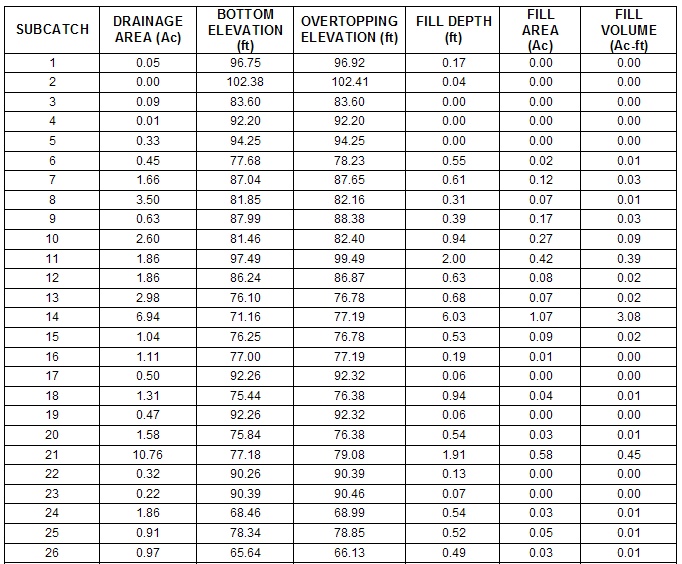
As with the first method of sink evaluation, review the table and try to establish criteria that can be used to distinguish between actual drainage basin sinks and unwanted pit pixels.
Once these criteria have been established, they can be used as the basis to fill the unwanted pit pixels.
Selective Filing
The 'Selective Filling' process involves filling all unwanted pit pixels based on a user-defined set of criteria (the criteria is typically determined from the 'Sink Evaluation' step).
Selective filling is completed using a CST script. The CST script can be accessed by selecting Export >> Macro Wizard, navigating to the 'Selective Filling' folder and selecting the 'Selective Filling.cst' script.
After you select "Run Macro" a check box list will open asking which criteria you would like to use select which pit to fill. For example, if you wanted to fill unwanted pit pixels based on a user define drainage area and fill (i.e., ponding) depth, the dialog box should look similar to that shown below.

Click to Enlarge Image
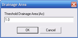
Next a series of dialog boxes will open (refer below). The number of dialog boxes is dependent on the number of different criteria that you have selected. Enter in the threshold parameter value in each dialog box that will be used to distinguish actual sinks from unwanted pits pixels. For example, in the dialog box below a threshold drainage area of 1 acre has been adopted. Therefore, any depressions with drainage areas of less than 1 acre will be filled, while depressions with drainage areas of greater than 1 acre will be retained.
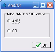
Next a form containing two radio buttons will appears asking if you would like to use 'AND' or 'OR' criteria. This selection only has an impact on the filling process if more than one filling criteria has been used. If 'AND' criteria is selected then all of the selected criteria must be satisfied in order for a pit pixel to be filled. If 'OR' criteria is used only one of the selected criteria needs to be satisfied in order for a pit pixel to be filled.
Now that the unwanted pit pixels are filled, the basin boundaries need to be redefined. First any existing basin boundaries (e.g., from the Sink Evaluation step) must be removed. This can be completed by selecting Subcatchments >> Delete Subcatchment >> Delete All Subcatchments. Also remove any existing lakes by selecting GIS >> Remove GIS DB >> Remove All Lakes.
Because filling of selected pit pixels has been completed, there will be some flat pixels introduced (as shown below by the red pixels). The flat pixels will need to be removed before the basin boundaries can be reliably determined. The flat pixels can be removed using the breaching algorithm and the same breaching algorithm parameters that were used as part of the 'Sink Prescreening' step. Alternatively, if you have used the 'Fill Depth' as one of your criteria, you can set the 'Max Elevation Gain' in the breaching algorithm to a value slightly less than the 'Fill Depth'. For example, if you used a 'Fill Depth' of 2 feet, you could set the 'Max Elevation Gain' to 1.9' to ensure that depressions areas with fill depths of 2 feet or greater are not breached by the breaching algorithm.

Click to Enlarge Image
Now the remaining pit pixels can be re-added as subcatchment outlets by selecting Subcatcments >> Other >> Add Flats and Pits as Outlets. It is recommended that a larger 'Cluster Tolerance' value be applied so that any adjoining pit pixels are not considered as separate outlets (A Cluster Tolerance of 15 pixels should be suitable for our example). Once this is completed, the basin boundaries can be delineated by selecting Subcatchments >> Map All.
The resultant basin boundaries are shown below. A review of the subcatchment manager verifies that only basins with a drainage area of greater than 1 acre and a ponding depth of greater than 2 feet have been retained.

Click to Enlarge Image