Subcatchments can be automatically delineated by CatchmentSIM on the basis of either user definition or automated assignment of subcatchment outlet pixels. The subcatchments are then mapped by applying the flow mapping algorithm to every pixel in the DEM and assigning each pixel as an attribute of the subcatchment outlet they first flow through. The program also calculates distance to subcatchment outlet and flow accumulation values at this time, and stores them in the hydrologic database.
As outlined previously, subcatchments are defined by their outlet pixels. There are a number of techniques to set the outlet pixels for the subcatchments including:
•Direct input of outlet pixel(s) row and column numbers into a dialog box;
•Individual selection of pixel(s) by clicking on the screen;
•Importing subcatchment outlets from a GIS database; and,
•Drawing an outlet line which is then automatically rasterised to derive the outlet pixel(s).
CatchmentSIM also includes three algorithms designed to automatically break-up a catchment into its major subcatchments by identification of significant points of lateral inflow or a target subcatchment size (Subcatchments >> Breakup Subcatchment). The first algorithm requires the user to set a target number of subcatchments and then the catchment is automatically divided into this many subcatchments, based on the largest jumps in the flow accumulation matrix. The second algorithm works by identifying all subcatchments formed by intersections of stream segments in the vector stream network of particular Horton / Strahler orders. The third algorithm requires the user to specify a target subcatchment size and the catchment is automatically divided into as many subcatchments as required to satisfy this criteria.
These algorithms can be used to reduce the subjectivity of subcatchment break-up and greatly increase the speed of the process. The second algorithm is probably the most objective approach because it neither requires the user to designate the subcatchment outlet locations nor the actual number of subcatchments. Furthermore, it could be expected that subcatchments of a similar Horton / Strahler order would have similar hydrologic properties.
These three subcatchment break-up algorithms are described in the following sections as well as in the Program Reference section.
Flow Accumulation Jump Analysis
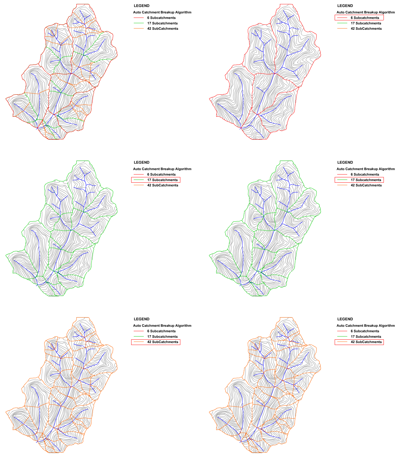
When using the flow accumulation jump algorithm (Subcatchments >> Breakup Subcatchment), the user simply designates a target number of subcatchments and the algorithm will automatically break up the catchment into the correct number of subcatchments. The algorithm works based on finding the largest jumps in the flow accumulation grid values between pixels in streams and their downstream neighbour which indicates lateral inflow of a significant tributary. Figure 26 illustrates the subcatchment break-up achieved by the automated subcatchment break-up algorithm using 3 different target subcatchment values.

Figure 26 : Flow Accumulation Jump Break-up Algorithm
Horton / Strahler Subcatchment Break-up
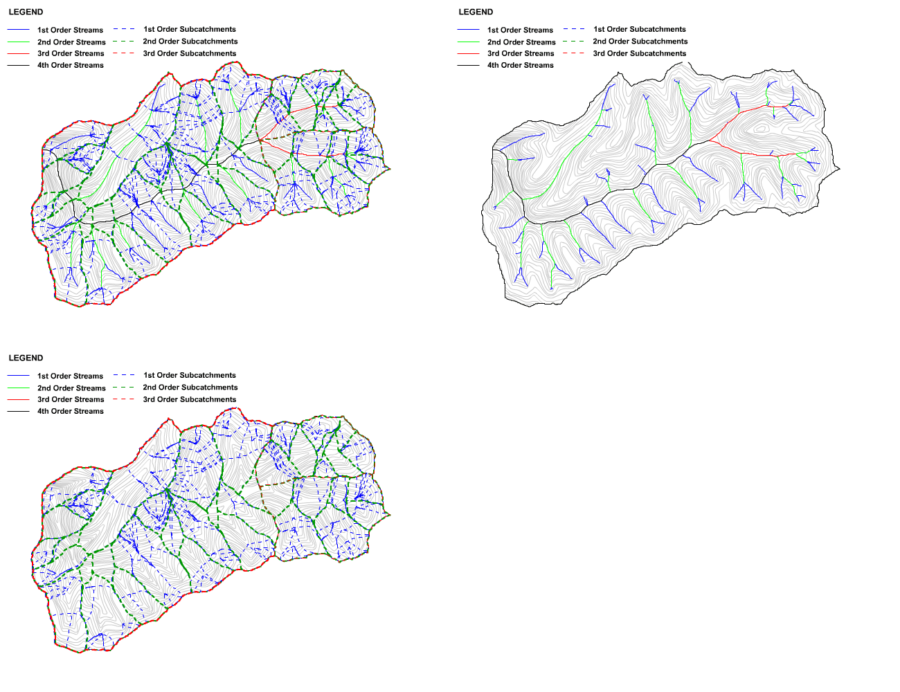
The Horton / Strahler based catchment break-up algorithm (Subcatchments >> Breakup Subcatchment) requires the user to first generate a vector stream network by selection of an appropriate SAT value. This can be based on quantitative analysis of SAT derived networks using the SAT comparison chart or by generation of a stream network that closely matches an observed stream layer. At this point, a user can select what order subcatchments to delineate. For example, if a user selects 3rd order subcatchments then subcatchment outlets will be placed upstream and downstream of all intersections in the stream network where two or more of the tributaries have an order greater than or equal to 3. As a result, the total number of subcatchments as well as the precise location of subcatchment outlets will be a function of the hydrologic properties of the vector stream network. An example of the subcatchment break-up achieved on a sample catchment when delineating subcatchments of differing Horton / Strahler orders in shown in Figure 27.

Figure 27 : Horton Catchment Break-up Algorithm
Utilising the Horton / Strahler ordering approach to catchment break-up provides the foundations for a standardised approach to lumped hydrologic modelling and reduces the guesswork involved in designation of the number of subcatchments and location of the subcatchment outlet points. For example, if a standard SAT is adopted for a specific geographic region then any lumped hydrologic modelling applied in this area could use Horton / Strahler based catchment break-up of a particular order to discretise the catchment. This would remove the subjectivity in selecting the number of subcatchments to use and their outlet locations, thus offering a more objective approach to catchment discretisation.
A comparison of Flow Accumulation Jump and Horton / Strahler Breakup is shown in the Key Challenges section.
Subcatchment target size
When using the subcatchment target size algorithm (Subcatchments >> Breakup Subcatchment), the user designates a target subcatchment size. The algorithm will automatically breakup the catchment into the number of subcatchments necessary to meet the target subcatchment size.
The subcatchment target size algorithm may be useful in the design of drainage infrastructure. For example, if a contributing catchment area can be correlated with the capacity of a standard stormwater inlet pit, the target size algorithm could automatically subdivide the catchment to meet the contributing catchment area threshold. The subcatchment outlet points determined by the algorithm would correspond to the optimal location for the standard stormwater inlet pits.