Map catchments
Next subcatchment boundaries must be mapped. GSSHA requires at least one catchment to be identified before running a simulation. A subcatchment outlet should be placed at all locations where you would like to extract discharge hydrographs. For this project we have three stream flow gauges where we have recorded discharge hydrograph information. Therefore, we would like to be able to extract simulated discharge hydrograph locations at all gauge location to assist with model calibrations. Up to 30 subcatchments can be added to a GSSHA project and hydrographs can be extracted at the outlet of each.
Please note that, unlike a lumped hydrologic model, the number of subcatchments added will not impact on the results produced by GSSHA. The subcatchments are used only to define where discharge hydrographs are to be extracted.
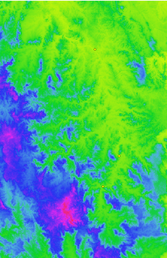
We will add subcatchment outlets at all of our stream gauge locations. First we need to know where the stream gauges are located. This information is contained in a 'StreamGauges.csv' file, which contains the longitude and latitude of all three stream gauges. To add the CSV file to project, click the ' ' button on the CatchmentSIM toolbar. Navigate to the 'GaugeLocations' directory and select the 'StreamGauges.csv' file and then click open. A projection dialog will appear asking you to specify the projection of the points located in the CSV file (this is because the CSV file does not store any projection information). Select 'Longitude / Latitude' at the top of the drop down list and click 'OK'. The location of the stream gauges should now be identified by a three yellow dots, as shown below.

Zoom in to each gauge location and add a subcatchment outlet at each location by selecting 'Subcatchments >> Draw Outlet' and then left clicking to create an outlet line that extends across the stream gauge point. Ensure the outlet line also extends across the main stream in the area.
The outlet line for the upstream most stream gauge (Bellbird Gauge), should look similar to the following:
The outlet line for the 'middle' gauge (Moy Pocket Gauge), should look similar to the following:
And the outlet line for the downstream stream gauge should look similar to the following:
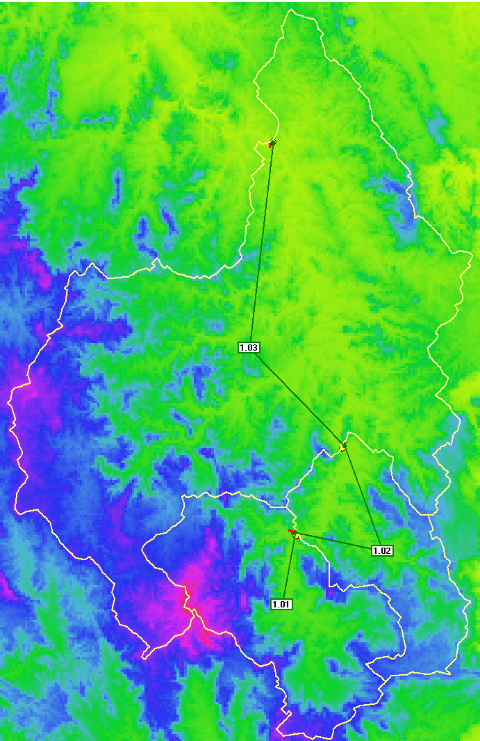
Now the subcatchment boundaries draining to each outlet should be mapped by selecting 'Subcatchment >> Map All'. The resulting CatchmentSIM project should look similar to the following (note that the subcatchment boundary colour was changed from red to yellow to make it more visable):

Map streams
Finally, preliminary investigations have indicated that it is necessary to incorporate 1-dimensional channel information into the gridded model in order to generate reasonable results. This is because the 1-D stream network enables more accurate definition of stream channel cross-section geometry and stream reach lengths. The stream network alignment can be defined automatically in CatchmentSIM based on the DEM and a user-defined stream area threshold.
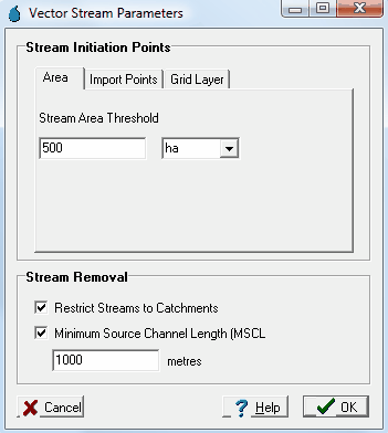
To map the stream network in CatchmentSIM, select 'Flow Mapping >> Generate Streams'. On the resulting Vector Stream Parameters dialog, ensure that the 'Area' tab is selected. In the drop down box select "ha" as the area units and enter a value of 500 in the adjoining text box. This specifies that a minimum of 500 hectares of land area must draining to any point in the project area before a stream is initiated. Also make sure the ''Restrict Streams to Catchments" check box is selected and also set the Minimum Source Channel Length to 1000 metres and then press the 'OK' button to the map the streams.

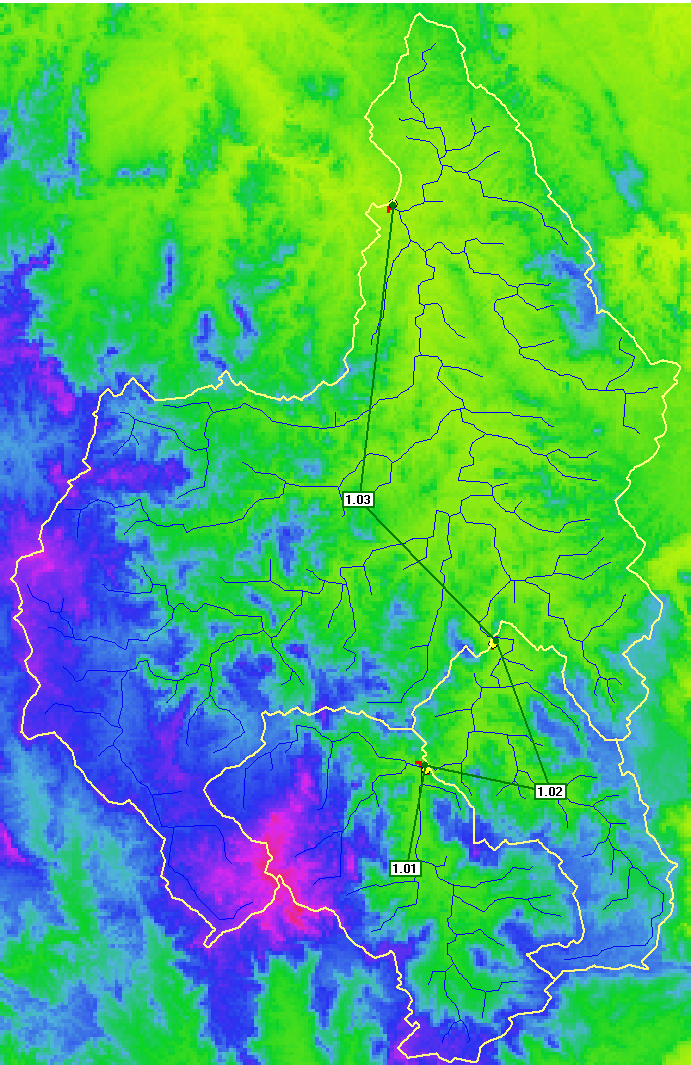
The resulting stream network should look similar to the following:

There are no definitive rules for determining how detailed a stream network needs to be (i.e., what stream area threshold is appropriate). However, it is considered important for a stream to be defined when the depths of flow across a particular area are predicted to be significant. This is because GSSHA provides capacity to assign different roughness coefficient values to the 2-dimensional overland flow domain and 1-dimensional channel domain. Flow depths within the 2-dimensional domain are typically quite shallow and higher roughness values are assigned to account for the higher effective roughness of vegetation. Flow depths within the 1-dimensional channel domain are generally higher and lower roughness values can typically be assigned to reflect the fact that most vegetation will be 'drowned out'. Therefore, it is suggested that channels should be defined at any location where significant depths of flow are predicted. However, it is also important that the stream network isn't too detailed as this will increase the simulation time.


