The 'Channels' tab is used to specify the characteristics of the 1-dimensional stream channel network across your study area.
Including channels in GSSHA is optional, however, our research indicates that they are necessary in order to achieve reliable results.
A description of each item on the 'Channels' tab is provided below.

Channel Routing Solution Scheme: the drop down is used to select the appropriate solution scheme for the 1-dimensional channel routing. If 'No Channel Routing' is selected then it is assumed there are no stream channels in the project and channel routing will be disabled. If 'Diffusive Wave' is selected, channel routing will be enabled and will be applied using explicit diffusive-wave 1-dimensional channel routing.

Node Spacing (metres): the node spacing refers to the distance between computation points along the 1-dimensional stream network. This value is populated automatically and is set equal to the raster grid size. Value equal to or close to the project grid size will typically generate acceptable convergence and results.
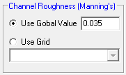
The 'Channel Roughness' section is used to specify roughness values for each stream channel segment. Users can specify a global value, which applies the same roughness value to all channel segments or they can use a raster grid if they would like to apply a spatial varying roughness value. A global value will typically provide reasonable results in most circumstances.
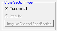
The 'Cross-Section Type' is used to specify whether a trapezoidal or irregular cross-section will be used to specify the channel geometry at each channel node. Currently only trapezoidal cross-sections are supported in the GSSHA interface.
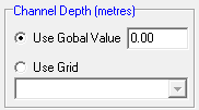
The 'Channel Depth (metres)' is used to specify the depth of the trapezoidal channel at each . You can specify a global value which applies a uniform depth to all channel nodes or apply a spatially varying depth value to each node by referencing an appropriate grid layer. As the channel depth will typically vary considerably across a large catchment, it will generally be necessary to use a grid value to specify the spatial variation in depth values. For guidance on how to develop a spatially varying channel depth grid, please refer to the example application.
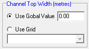
The 'Channel Top Width (metres)' is used to specify the top width of the trapezoidal channel (i.e., the distance between the top of the channel embankments). You can specify a global value which applies a uniform width to all channel nodes or apply a spatially varying width value to each node by referencing an appropriate grid layer. As the channel top width will typically vary considerably across a large catchment, it will generally be necessary to use a grid value to specify the spatial variation in width values. For guidance on how to develop a spatially varying channel top width grid, please refer to the example application.
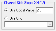
The 'Channel Side-Slope (XH:1V)' section is used to specify the side slope of the trapezoidal channel at each stream channel node. The value is input as the vertical displacement for a horizontal displacement of '1' (i.e., you are inputting the 'X' value in XH:1V). Users can specify a global value, which applies the same side slope value to all channel segments or they can use a raster grid if they would like to apply a spatial varying side slope value value. A global value will typically provide reasonable results in most circumstances.

Include Backwater Effects: If checked, GSSHA will include backwater effects on overland when 1-dimensional stream water surface elevation is greater than 2-dimensional overland flow surface elevation without allowing water in channel to flow back onto overland. This will generally result in an increase in computational time.
Allows Spill from Channel to Overland: If checked, GSSHA will allow water in channel to flow back onto overland flow plane when stream elevation is above top of bank and the adjacent overland cell elevation. This will generally result in an increase in computational time.
